|
Building the base
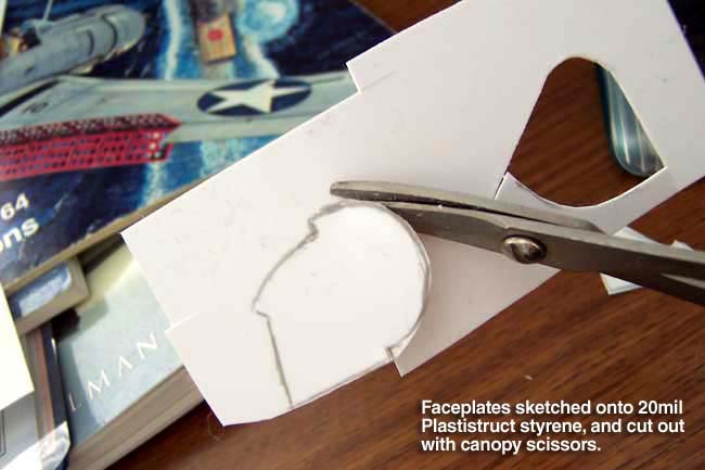
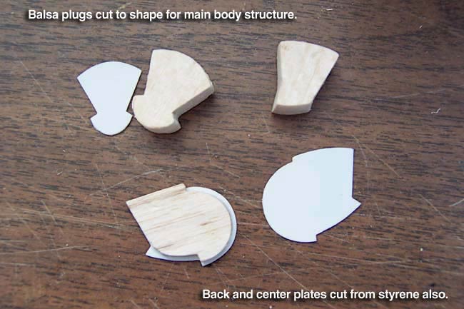
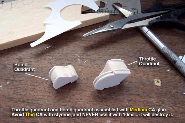
To begin building the base for each control, I start by hand-sketching the profile onto a piece of 20mil styrene sheeting. Next I cut it out using a good pair of canopy scissors. This is important, as canopy scissors are essential for getting intricate cuts and curves when cutting out your styrene details... do not use regular scissors. These pieces will be the "faceplates" of each base, then I cut the backplates, and the centerplate for the throttle base. Once these are cut out, I made the balsa plugs that serve as the core of each base. These are all assembled using Medium CA glue, do not use Thin CA on styrene.
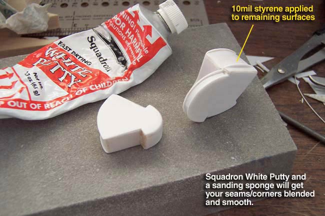
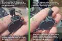
With the front and back surfaces covered with 20mil sty, you can now surface the perimiter with 10mil styrene. Next I use a medium grit sanding sponge to sand all joints into a smooth corner. Here's a tip... always sand the corners/joints of your details to a slightly smooth/rounded corner. Very sharp corners look unrealistic and make your components look phoney. This also hides most unsightly seams, but bad ones can be better hidden with a quick shot of Squadron White Putty and another sanding.
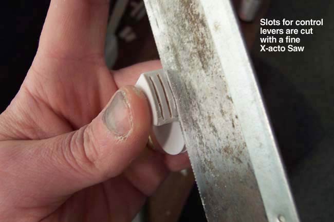
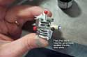
Lastly, I cut slots into the tops of each base with an X-acto saw. These will be the slots that the levers slide in. The slots can be further widened and cleaned up with an X-acto knife.
Making levers
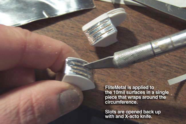
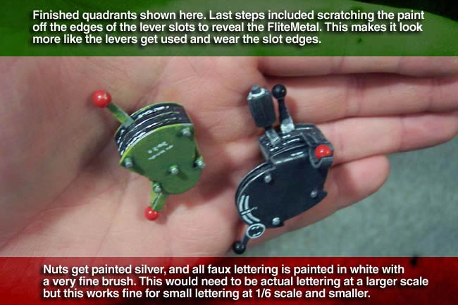
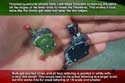
 I then apply FliteMetal to these top surfaces and burnish it down good. This will also allow you to see the impression of the slots so you can open the FM material back up with a knife where the slots are. Later, after painting, we'll be able to distress the paint revealing metal to simulate the wear of the levers sliding back and forth. I then apply FliteMetal to these top surfaces and burnish it down good. This will also allow you to see the impression of the slots so you can open the FM material back up with a knife where the slots are. Later, after painting, we'll be able to distress the paint revealing metal to simulate the wear of the levers sliding back and forth.
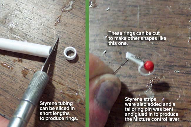
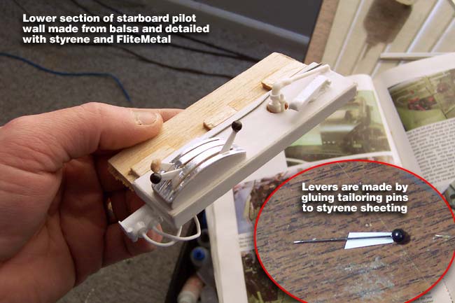
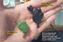
Next I start working on the actual levers themselves. These are most easily fabricated from standard "tailoring pins" which come in multiple colors and sizes. These pins can be bent to different shapes easily and provide a nice round ball at the top without any additional fabrication. However, most levers were not mounted on a "pin-like" post, they were on a variety of other flat metal stocks. Here you'll see me fabricating a pretty wide assortment of lever styles from these tailoring pins.
The Blower Lever
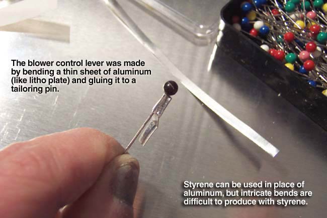
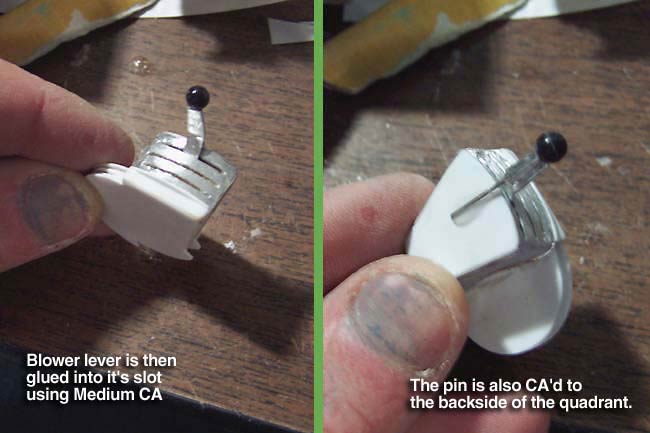
You can CA different materials onto your pins to simulate the flat "plates" that the actual levers would have been mounted on. In my first example, the blower lever, I actually used a small strip of thin aluminum which could be "z-bent" into the proper scale shape, and retain good bend corners. Other times when the bends aren't as critical, I'll just use 10mil styrene to act as the plates. The blower lever was then glued into the base and the pin was glued to the backside of it.
The Mixture Control Lever
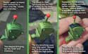
Moving on to the mixture control lever, I started by cutting a slice of the end of a piece of styrene tubing. This slice got cut in half to form a "half-circle". Next a piece of 20mil sty was glue to it and a bent pin was inserted into the fixture.
The Throttle Lever
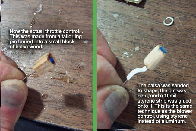
The throttle lever was done the same way as the blower lever, except I used styrene instead of aluminum this time. But first, a pin was inserted into a balsa block and the block was shaped into a handle. Then the pin got bent and the sty plating was added.
The Prop Pitch Lever
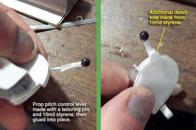
The pitch control lever was a pretty straightforward "pin and styrene" approach. Some additional small detailing was added from 10mil styrene as well, and the pin was glued into the balsa base.
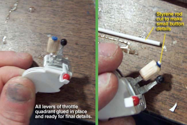
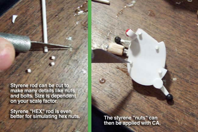
With all the levers in the upper quadrant installed, I then added the last few minor details to with styrene rod. The hex nuts on the faceplate were easily made by slicing small pieces of styrene hex rod and gluing them in place.
The Bomb Arming Lever
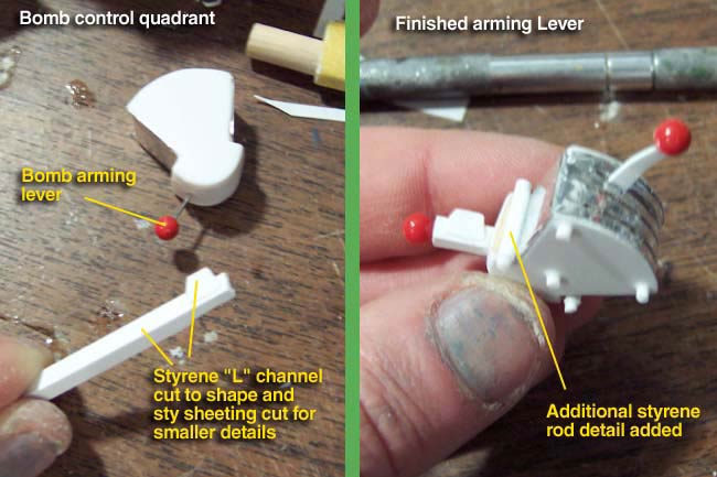
The bomb arming lever was done a little differently. I started by gluing a pin into position in the lower base. Then, I fabricated the unique plating out of a piece of styrene L-channel and additional "snippets" of 10mil sty sheeting. This was then glued onto the pin and additional bolt & nut details were made from styrene rod and hex rod.
The Bomb Release Lever
The bomb release lever was a simple lever done just like the prop pitch lever listed above.
Painting
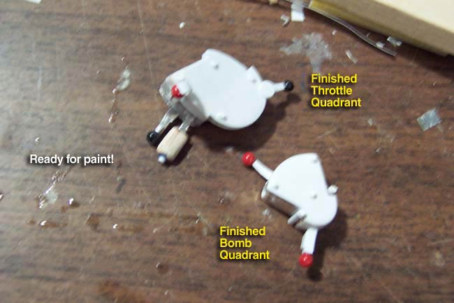
 With all quadrant bases done and levers installed, I'm now ready to paint. Usually I mount all components onto the wall and primer everything before painting. This was a unique situation that required a different approach. The intricate/complex shape of these controls protruding out off the walls a good ways meant that getting them painted properly on all sides would be difficult after mounting. With all quadrant bases done and levers installed, I'm now ready to paint. Usually I mount all components onto the wall and primer everything before painting. This was a unique situation that required a different approach. The intricate/complex shape of these controls protruding out off the walls a good ways meant that getting them painted properly on all sides would be difficult after mounting.
Therefore, I went ahead and painted them "offline" and would mount them later. This step starts by feeding flat black down into each of the lever slots to get a good deep black recession for each slot. Next, I paint each quadrant in their respective base colors. This would be black for the upper quadrant and green for the bottom.
Scale Black
The black upper quadrant should not be painted with black right out of the jar. Never use pure black, or white, on any scale plane. This is difficult to explain, but what you are going for is "scale color" that looks more realistic than paint right out of the jar. There are a few reasons this is an important topic...
 First, very few things in this world are true black or white. This is especially true of warbird components that are exposed to elements and wear and will rapidly shift in color to a slightly dirty/aged black and white. Hue, saturation, lightness and specularity are all attributes of color and finish that we all recognize on full scale items. First, very few things in this world are true black or white. This is especially true of warbird components that are exposed to elements and wear and will rapidly shift in color to a slightly dirty/aged black and white. Hue, saturation, lightness and specularity are all attributes of color and finish that we all recognize on full scale items.
When you scale down an object to 1/5 scale, you don't scale down your eyes/vision, nor the physics of light and color. Therefore a model will look like "a model" unless you compensate by adjusting your colors. In the case of black, this means you need to mix up what scale painters will call "scale black."
My recipe for scale black varies depending on what "shade" of black the component should be in the first place. Yes there are many shades of black and many shades of white. Just go to a paint store and look at the paint chips... you'll get the idea. For my cockpit interior, I like a scale "cobalt black" which starts with Flat Black, add a dash of PolyScale "Dirt" and Flat White. Lastly, a "half -dash" of Insignia Blue. Next is the green lower quadrant, which I base coat with Model Masters Zinc Chromate Green right out of the jar.
More realistic details can be obtained with a little extra effort in weathering and distressing the paint. |
Weathering & distressing
Most scale modellers understand the value of weathering on the exterior of a warbird, but very few see how important it is to do so on your interiors. These techniques can make the difference between a really nice cockpit and a memorable "holy crap" cockpit!
Weathering is a "broad term" that is applied for a lot of applications. In it's truest sense of the word, "weathering" means applying paint techniques that make a model "appear" to be soiled, worn and distressed from a combination of natural weather & elements, as well as wear from human interaction with components.
However, the term and technique also applies to simply "pulling out 3D detail" on even a pristine/showroom class model... or a cockpit/interior. In other words, when you scale a model down, the detail scales down but the light shining on it doesn't. Therefore, you need to apply "weathering techniques" to make relief look more realistic.
It is done more subtle and with different colors than when weathering to simulate distress and wear, but the techniques are the same. These techniques fall into 3 basic categories...
1) Base coat mottling
2) Wet Washes
3) Dry Brushing
The best job you can do will utilize all 3 of these techniques, which would require an extensive document to explain. Which technique is determined by the object, the detail, the "effect" desired, and especially the paint medium being used.
|
|
Enhancing relief
The first phase of this process is to simply "enhance" the 3D relief of your components. This means you need to make the recessed areas darker and the raised areas lighter. The areas in between would be a blend between the two, mostly made up of your primary base coat color.
In other words, think of your model as a 2-dimensional topigraphical land map. The high points of the mountains would be light colors, and the valleys and rivers would be dark colors... representing topigraphical altitude. You need to do the same to your model components, only to a lesser, more subtle degree.
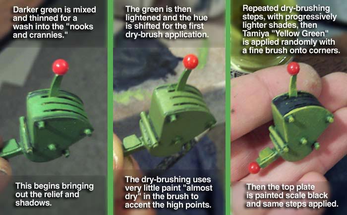
This starts by doing a dark wash of very thinned down paint into the low areas and around the base of protruding details (like nuts & bolts). This would be a darkened version of your base color, mixed up like water colors. Next you might want to go back with the base color and blend any hard edges of the wash so it looks more natural.
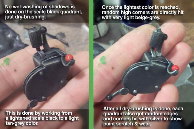
Now you want to start working through lighter shades of your base color using a "dry-brush" technique. This means you should use very thick paint, and very small amounts worked deep into your paintbrush. The paint should be almost dry and the brush pulled along the surface so that it hits only the high points. Do this in progressive steps to build opacity and lighter shades to the highest points.
I have found that in the case of black, your lighter shades will need warmed up with a dash of Tan/Dirt to avoid a cool grey highlight. In the case of the green, I add a dash of Tamiya Yellow Green as I progressively lighten my shades. Lastly I will take a 00 brush and randomly hit the extreme high points, corners and edges with straight Yellow Green. This really makes it pop and look natural.
Weathering
The degree of relief ehancement done above is actually also the first step in the weathering phase. The more you enhance the relief, the more weathered it looks. But, to take it further, you need to add the dust, dirt, grime and grease that makes it look even more believable. This is done by mixing various shades of the Dirt color and doing a drybrush technique in areas that would collect dust and dirt... mostly the top/horizontal surfaces.
Shades of thinned down dark grey are applied with the 00 brush in nooks and crannies and streaks from oiled/greased areas. This can be done in progressive steps to build opacity in appropriate areas.
Now you go back and do a dry-brush "scrubbing" of various shades of your base color to "mottle" the flat surfaces and make them look faded, stained and dirty. Lastly I will sometimes use an airbrush with thinned lightened "Dirt" and shoot it vertically straight down onto the component in it's upright position. This will act and look just like real dust settled onto the tops of details. This is a very subtle application and can easily be overdone.
Distressing
Distressing is a term I use when I refer to simulating the degredation of the paint itself. This could be paint wear, paint peel or paint abrasions/scratches. This is easiest on the components that have FliteMetal underneath the paint.
All you have to do is file or sand the paint back to get a feathered paint wear effect down to the bare metal. To simulate scratches, like on the edges/corners of details, just scrape it with the edge of your knife blade.
When I don't have FM under the paint, I just brush Testors Silver Enamel on with a 00 brush. The key to this is not overdoing it, and do it in a "natural wear" pattern. This means lightly hit corners and edges in a random dispersion. It also means applying larger, more "organic" patterns to represent paint peeling. Paint peeling looks most realistic when you do it up to and around rivets, leaving paint on the rivet itself.
Markings / Labeling
The final step of painting is to add the tiny markings, labels and graphics that are on the nameplates, dials etc. On 1/6 scale planes and smaller, this can usually done by simply using a 00 brush and some white paint to "simulate" the markings where needed.
On larger scale planes, this would not work for most markings which would need to have actual labels produced as decals or using a laser printer.
Some nameplates were metal with reversed out lettering in silver/metal. This can be done by making a plate from FliteMetal, paint it black, then scratch faux lettering into the paint with the tip of a knife blade. The FM material can then be applied just like a decal, with metallic lettering on the plate.
|

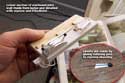
Secure glue joints are best made by using a pinning method with styrene rod. |
Secure mounting
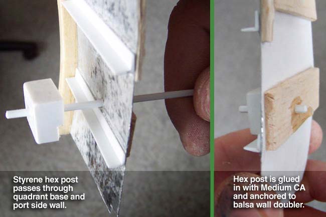
With the control quadrants all painted, I then started working on a secure mounting scenario. This usually means running a support post into the component, and all the way through the cockpit wall. This makes your glue joints much stronger and really helps fight the vibration that resonates to an imminent breakdown of your cockpit.
To really get the best result, I use a styrene hex rod which I will bury as deeply into the "component" as possible, if not even all the way through it. Next, I'll drill a hole in my wall panel and run the hex post all the way through it, gluing everything well, but also adding a good "mushroom" of glue on the post sticking out the backside of the wall.
In the case of these control quadrants, I had an additional piece that went between the quadrant and wall. This was a "standoff bracket" that held the controls out off the wall a bit. I made these out of balsa with styrene sheeting and some FliteMetal. The more complex upper bracket also used some styrene I-beam and L-channel. The hex support rod was then set up to go from inside the quadrant, through the balsa brackets and finally through the walls.
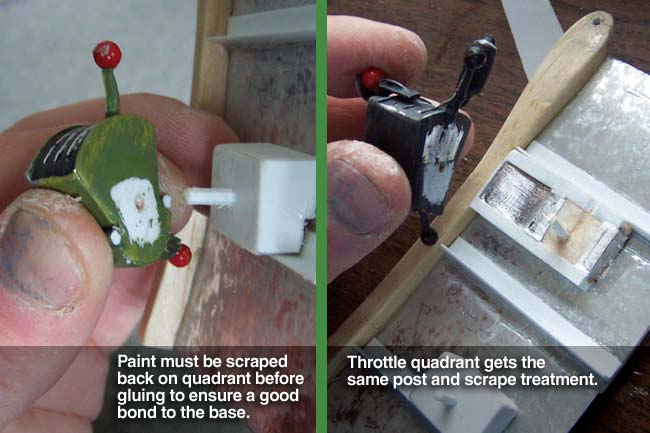
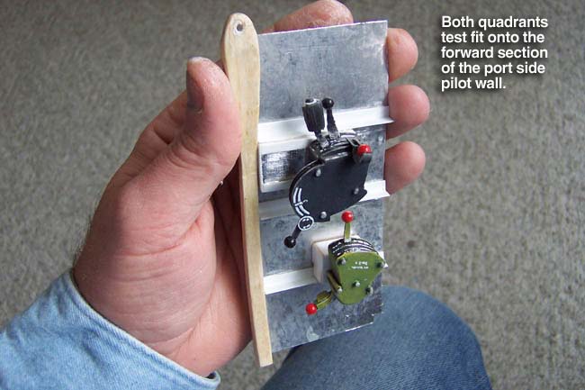
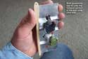
Note that it is very important that you scrape back the paint on any glue joint surfaces as the paint will act as a barrier to the glue, causing you to just glue paint to paint and end up with a very poor joint. It's also a good idea to scuff sand the styrene in the area of the glue joint for better adhesion. At left you see the painted controls test fit onto their mounts before removing them to finish up the wall section.
|
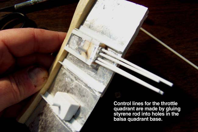
Control lines, hoses and conduits
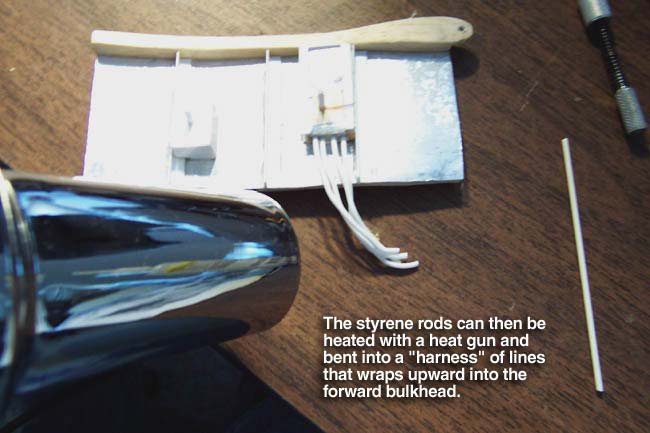
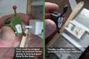
To really make your controls complete, you need to add the corresponding control lines, hoses and conduits. These are most often fabricated from styrene rod of varying diameters. This rod can be bent by heating it with a heat gun and bending it to shape, usually before installing.
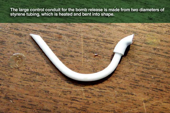
Sometimes I will also just use pieces of wiring like that of an aileron extension. For larger conduits, I'll use either styrene tubing or micro pushrod tubing. You can simulate pipe fittings and unions by using the next size up of styrene tubing. Slide it on like a sleeve and glue it in place like in the picture below.
Getting these securely glued in place can be a challenge. When gluing sty rod on, I'll usually drill a hole for the rod to recess into, giving it a stronger glue joint. When gluing tubing on, I'll make a "pin" out of sty rod, bury it in the hole, and then slide the tubing over it. This produces a "snap-on" pinning feature that gives you a really good joint. Loose ends like that shown in the far right pic above, can be glued into a balsa plug that you can then glue to another surface out of sight.
 |
Final assembly
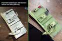
The pics a left show the finished wall section made of posterboard and Flitemetal, and various balsa and styrene details. Next to it you see the same section after painting and weathering.
The bottom pic shows the finished section with the control lever quadrants permanently glued in place with Medium CA. The end result it a complex and very believable wall section with complete details, controls, control lines, etc.
The techniques in this article can be extrapolated to a variety of interior components using the same or similar materials and steps. Future articles and/or videos will show you how I do other components using these techniques.
|
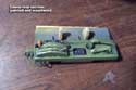 |
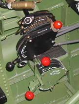
Another example
Here's another example of a control quadrant that was fabricated for the starboard side of my SBD. The primary lever cluster which controlled the flaps and dive brakes was produced using the same basic techniques as shown in this article.
If you have interest in seeing more on how I did this and other cockpit components for my SBD-5 Dauntless project, visit my SBD construction web site. It has complete pictorial, step-by-step documentation of my project from concept to finished project. Click here to visit my site.
|
|
 Now let's get started on the actual fabrication of the control quadrants for the throttle and bomb mechanism. The techniques to follow are a good cross-section of those that I use throughout my cockpit work. Same idea, just different components when I move around on the interior fabrication.