Click logo to return to home page. ]

 
Home>Forums>Show Your Stuff!!!>A Good Days Flying and Fun. Post Reply   New Topic   
Forum Jump 2 Pages 1 2
] ] ]
]
Author / Post
Avatar User Offline fwjeff
Site Supporter
Site Supporter
Joined: April/23/2013
National Flag of United States United States
Posts: 2374
IP Logged
Posted: September/02/2019 at 4:18pm  Quote
 
Sad to see the damage, she was a beauty! Glad to see the repairs well under way!

__________________
Jeff
 
Back to Top  Printer Friendly Version  Profile  Search 
 
Avatar User Online kuhn
Site Supporter
Site Supporter
Joined: February/08/2009
National Flag of Bulgaria Bulgaria
Posts: 2901
IP Logged
Posted: September/17/2019 at 10:01am  Quote
 
So after a few weeks of producing my Brian Taylor Typhoon kits for Sarik Hobbies it's back to the re build.

Next up was to re-establish the exact engine thrust line for the OS 120 E so I could get the cowl nose ring and spinner back plate positioned.

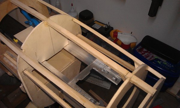
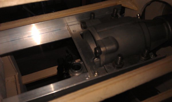
To mount the engine I used two 20 mm x 20 mm aluminium angles as beams with the old aluminium crush plate as a spacer just behind the engine. These ran from the back of the tank bay box forward and was glued and screwed to the top of the tank bay box.

Pic below of engine bearer beams and the spacer.


Engine bearer beams.


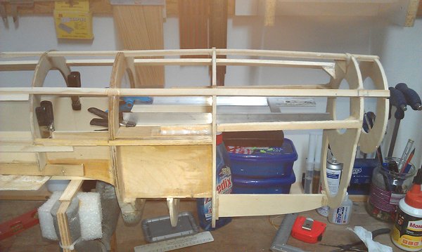
Still nice and level.


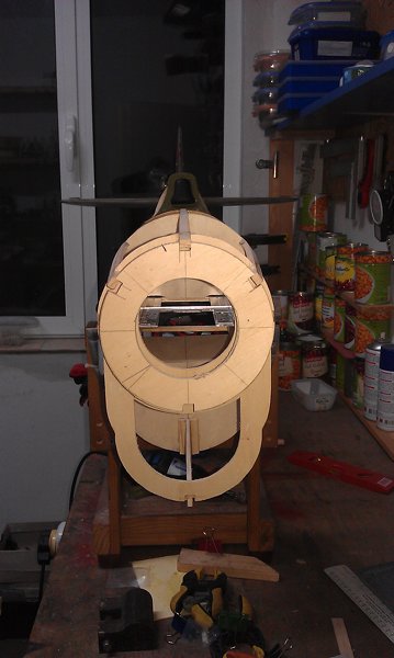
Spinner back plate positioned.


Engine bearers being glued in. Later countersunk screws where added.


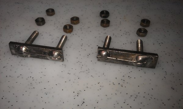
I made these to hold the engine securing bolts. Old idea to stop bolts turning when tightening the nuts.


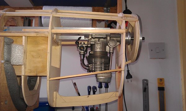
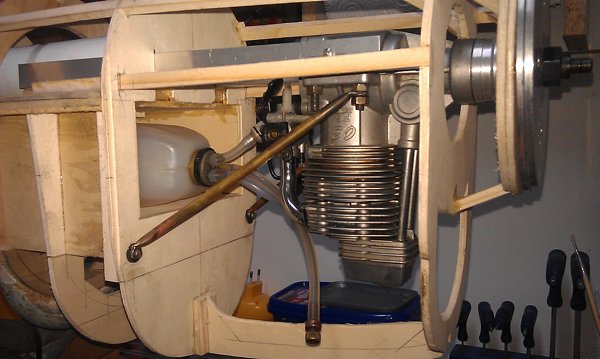
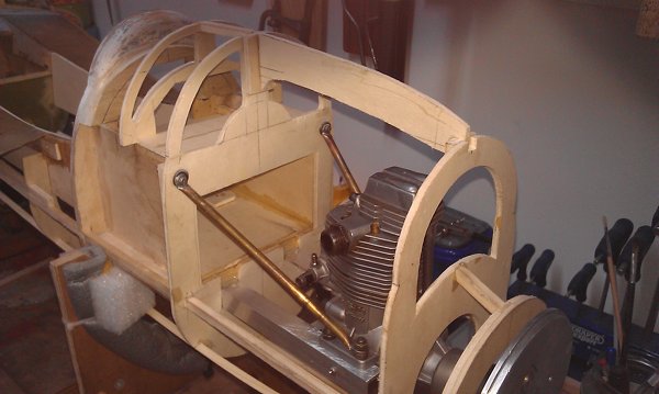
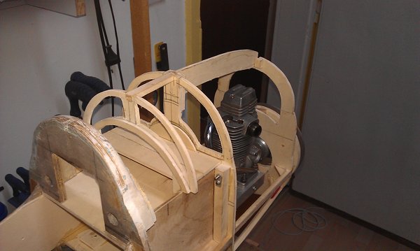
Engine being trial installed.


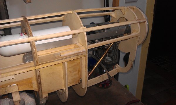
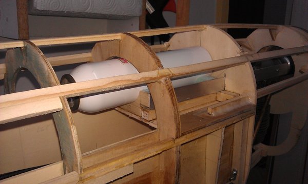
The old brass tube engine braces were re-used. 
Tank positioned to see where the inlet lies relative to the carb spray bar.


Retract air bottle sits here in a cradle shaped to hold it. Siliconed into place.


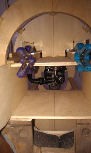
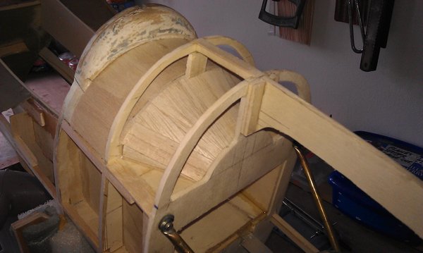
Air flow from the cowl front, over the engine and out the bottom 
was achieved by following the full sized principle. Formers were dremelled to create apertures.


A shelf, just above the tank bay box floor (fuselage is up side down) 
was made up against former 3. The flight batteries will live here and be 
accessible from the wing seat area. 


This area was planked and will be glassed against oil from the engine bay.
The flight batteries sit in that cone shaped area.


That's it for now. Wing seat area next.


__________________
Kuhn

If in doubt. Don't!
Flying: HIGH!
Building: Getting my Mo Jo back slowly to finish a few projects.
 
Back to Top  Printer Friendly Version  Profile  Search 
 
Avatar User Offline Sparky
Lifetime Site Supporter
Head Curmudgeon
Joined: February/10/2004
National Flag of United States United States
Posts: 7091
IP Logged
Posted: September/17/2019 at 11:12am  Quote
 
The idea of the diagonal brace looks good. What is the material being used? Have you done this successfully in the past?
The crimped ends are a weak point and likely to fracture from vibration.
I would suggest for your consideration using a section of your angle aluminum piece just cut off the angle part so you have a flat piece of aluminum and run it from the side of you angle aluminum motor mount up front back to the firewall where it attaches to a block on the firewall so it doesn't have any bends.

Sparky

__________________
Brown County, Indiana
TopRC FW-190, Zenoah GT-80
Bates F6F Hellcat, Saito FG60-R3
Gamma RIP

 
Back to Top  Printer Friendly Version  Profile  Search 
 
Avatar User Online kuhn
Site Supporter
Site Supporter
Joined: February/08/2009
National Flag of Bulgaria Bulgaria
Posts: 2901
IP Logged
Posted: September/17/2019 at 11:34am  Quote
 
Sparky,

Thanks for the concern.

Those are over 21 years old and survived the crash.

They are hollow brass tubing about 4.5 mm in diameter. 

The ends have been flattened and silver soldered after the holes were drilled.

The soldering was run up past the bends as well. Very strong.

Where they are bolted to the fuselage the the bolts run through rubber grommets to aid in damping vibration.


__________________
Kuhn

If in doubt. Don't!
Flying: HIGH!
Building: Getting my Mo Jo back slowly to finish a few projects.
 
Back to Top  Printer Friendly Version  Profile  Search 
 
Avatar User Offline dd71
Basic Member
Basic Member
Joined: August/15/2008
National Flag of Italy Italy
Posts: 689
IP Logged
Posted: September/17/2019 at 2:40pm  Quote
 
nice and neat work Khun!!! some time is necessary for start a repair/rebuilding but at the end, when she flays again ... 
Cheers
Daniele


__________________
"All of the best information on a subject arrives the day the model is completed, and proves conclusively that what you have done is wrong."
 
Back to Top  Printer Friendly Version  Profile  Search 
 
]
] ]
Forum Jump 2 Pages 1 2

If you wish to post a reply to this topic you must first login
If you are not already registered you must first register


  Post Reply   New Topic   

] ] ]
]
   ]
Similar topics you might be interested in...
Glassing a hinged ARF?
PCM - Flying a 109
Duxford Flying Legends 2015
Awesome CAD Design and Build
You cannot post new topics in this forum
You cannot reply to topics in this forum
You cannot delete your posts in this forum
You cannot edit your posts in this forum
You cannot create polls in this forum
You cannot vote in polls in this forum
]
] ]

Home Icon Portal Home   Forum Icon Forum Home   Forum Icon Your Privacy

Copyright © 2003-2024, RCSCALEBUILDER.COM, All Rights Reserved