By Phil Clark
Since your beautiful
scale model spends virtually all of its life on the ground, it is here where
your admiring public will stand and scrutinize the detailing you have applied.
While the aircraft may look great in the air, the illusion can quickly evaporate
under closer inspection. Many big models on the show circuit are just big - and
little else. Foam and brown paper have their place ( for packaging, not models )
but when you build a scale model, it is meant to be a miniature of the real
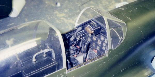
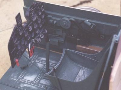
aircraft. The most obvious place to spoil a scale model is the cockpit.
|
What’s the point?
I see
detailing a cockpit as a personal preference; I know it is there, so
it requires detailing, even if no one else will ever see it. If you
feel the same, then go for it. If not, there are however, several
things that must be considered before commencing such a task. Is the
model going to be used in competition? If so, judging is often done
from several feet away, so going down to the last switch and dial
may not be necessary.
Secondly, cockpit detail will add weight, weight that could be
un-necessary to the finished article, can the model take the extra
weight? Do you have enough power? Will an extra few ounces affect
the flying characteristics in any way? Third, will the cockpit tub
get in the way of other items within the model, e.g.: - servos, push
rods etc… remember, the cockpit area is the normal place to hide all
the radio gear etc…And lastly, with the canopy on, how much of the
cockpit is actually visible? If it’s only the instrument panel, why
go to the trouble of doing the whole lot. If you want to go the
whole hog and do a sliding canopy too, ignore my last statement!! |
 |
|
Even the
simplest of efforts can dramatically improve the appearance of the
"greenhouse" !!! |
Ok, lets go through
these one by one. Competition use, probably not, I’m assuming you just want to
have a go at producing a convincing looking cockpit for the sake of doing it,
this hobby is meant to be fun after all! Weight, yes, it will add some, but only
a few ounces on even a large model. When we have 40 or 50cc in the nose, 3 or 4
oz isn’t going to affect things that much, but if we’re talking about a .60 size
scale model that only weight 6 or 7 lb anyway, the extra can start to become a
problem, so a compromise must be made.
Will it get in the
way? Quite likely, but again, with a large model, there are lots of other places
to hide all of the other bits and pieces, especially being that we often try and
mount our servos a lot closer to the control surface than we would with a
smaller model. Even on a smaller 60 / 70’’ model, with careful planning and a
bit of thought, everything can be made to fit quite nicely. You will just have
to make the decision to detail the cockpit as you start building, not complete
the fuselage, and then decide to have a go.
How much can you
see? This differs from subject to subject. Obviously, an open cockpit model such
as a Stearman Kaydet is an ideal candidate to receive the full treatment, on the
other hand, a P-51B Mustang with it’s small framed high back canopy maybe does
not deserve the same treatment. There isn’t a lot of glazing to look through,
plus there is a lot of framework to get in the way and spoil the view of all
that detail. The majority will say, ‘if you can’t see it, why do it’. On the
other hand, if your subject has a big ‘bubble’ canopy, P-51 D, Thunderbolt,
Bearcat etc…. then a fair amount of the cockpit will be easily visible, so a
good reason to make the effort to add a little detail.
References
Ok, so we’ve decided
what sort of level of detail we’re going to aim for, the next thing to do is to
get hold of as much reference material as possible. The basic information that
will be required is, where exactly does the cockpit tub start and finish? How
wide it is? Seat position etc…. all of this can often be taken from a good set
of 3-view drawings that include fuselage sections, cut away drawings etc….
Next comes detailed
information on what is actually contained within the cockpit. In the main, books
can supply all of this information, the range of ‘Squadron Signals’ publications
are a good starting point. Specialist aviation bookshops can also supply copies
of ‘Pilots notes’ for a huge range of subjects. They are pretty heavy going if
you do decide to read, but the quantity of detailed internal pictures of all
areas of the airplane give a wealth of information.
Lastly, if you’re
fortunate enough to live near a good museum that happens to have one of your
chosen subjects on display, a ‘Can I please have a look and take some photos’
phone call is worth a go. I have done this on several occasions, and the museum
staff are often more than happy to help out. Both ‘The Fighter Collection’ based
at Duxford, and the RAF Museum at Hendon in London are both well worth a visit.
Getting started
If we look at the
cockpit as a whole, the ‘Where do I start’ question is likely to arise. What is
required is to break the cockpit down into the simplest format possible. This
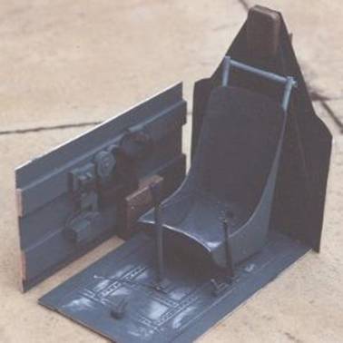
is, floor, front (instrument panel), left and right side walls, and rear wall.
First task will be to produce these 5 panels to the correct size from ‘light’
sheet balsa. Assembling these will give us the basic ‘tub’ in which to work in.
|
 |
OK, this
is my first strange suggestion, don’t glue these panels together
yet, if you do, then you will have a relatively small area to work
with etc…making adding all of the internal detail quite fiddly. If
you leave the panels as individual parts to work on, adding the
detail becomes much simpler, the tub can be assembled at the end
once all of the detail has been added. |
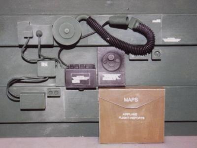
With the 5
panels produced, the first job is to detail these to represent the internal
cockpit walls, minus all of the instruments, boxes, levers etc…. Most cockpits
have some form of internal structure exposed (formers, longerons, bracing etc…)
which all has to go on before the bulk of the extras. If this structure takes
the form of shaped extrusions (‘L’ or ‘T’ sections), a trip to your local
plastic models and railways specialist will produce a wide selection of 12’’
long plastic sections in a vast range of shapes and sizes to do the job. This
stuff is great to work with, very light, bends easily to shape and is easily
glued.
|
The
other consideration is how do we achieve the ‘metal’ effect on these
panels. Several coats of sanding sealer and a coat of aluminum paint
is an option, but far simpler and faster is skinning each panel with
‘Litho Plate’. This stuff is really useful, and normally available
‘free’ from your local lithographic printers. They print on one side
only, leaving the other nice and clean, but chuck it out after one
use. A quick phone call can normally acquire a few sheets that will
last you years. The best adhesive to attaching the litho is a
contact adhesive. Epoxy and cyano both work, but as the litho is so
smooth, there is no ‘key’ for the glue to adhere to, a little
vibration etc… will start to loosen the litho, and it will
eventually drop off! |
 |
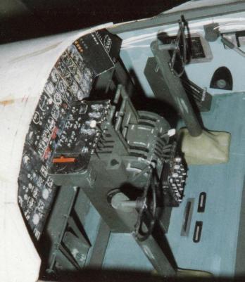
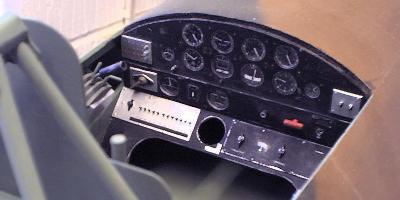
Instrument panels
The instrument panel
is probably the easiest panel to complete first, especially if you have good
documentation. To try and get a 3-D effect, rather than a ‘stuck on, sports
model’ effect, the panel must be made of several layers of material. The face
panel is the most important, so take your time. Most panels were metal on
full-size aircraft, so we must use a smooth material, unless you feel like
applying 4/5 coats of sanding sealer to thin ply, with a rub down between each
coat!. I’d go with plasticard or ply, skinned with litho plate.
First task is to
accurately cut the dial holes to the correct diameter, and in the correct
place. Remember, not all dials were the same size, so check on your
documentation. To accurately cut these holes in the thin material, try this
method. Clamp your faceplate material, (oversized for now, not cut to shape) in
between two thick pieces of ply, about ¼” will be fine. Mark the dial holes onto
the wood, and drill through the whole sandwich, preferably on a pillar drill to
keep all the holes nice and square. Once done, remove the faceplate, and you
should have nice clean holes, any splintering etc… will occur on the ply, not
the faceplate. With the hole done, the face plat can be cut/trimmed to the
correct size a shape.
|
 |
Next
step is to add the instrument bezels; these are the raised parts
that surround each instrument. If you have several instruments all
the same size, it is worth making one master, taking a silicone
mould off that, then moulding as many as you require in casting
resin. If not, and most of your dials are different, you have no
alternative but to make each and every one individually. This
method has worked well for me. |
Again using
plasticard, cut a hole the same diameter as the one in the panel, and then trim
around the hole to create the body of the bezel. To create the lip, wrap soft
solder around a tapered round paintbrush handle to create a ring, cut the ring,
and cyano around the hole on your bezel. The screw heads in the corners of the
bezel can be applied as small blobs of PVA or aliphatic glue through a syringe.
Once everything is dry, give each bezel a quick blast of high build primer to
fill in any small imperfections, then glue to the faceplate.
Any other raised
areas, screw heads, etc… can all be built up in the same way. With the faceplate
complete, it can now be painted and weather. Again, check your documentation,
not everything was black!! Americans used various ‘greens’ and the Germans ‘gray’,
be sure to get it right. If you’ve used white plasticard, you’ll need to give
the plate a coat of silver before the top colour if you wish to weather the
panel, bringing the silver through from underneath. With the silver and top coat
applied, the easiest weathering technique is to lightly scrub the panel with
fine grade ‘wire wool’, ‘000’ or ‘0000’ grade is about right. Any more coarse,
and it will scratch the paint, the fine wool actually polished the paint,
wearing it thin on high spot, eventually bringing the silver through, giving a
much more subtle effect.
The next step is to
add the glazing for the instruments. Using thin clear acetate sheet, cut a piece
the same shape as the entire dashboard, and glue it to the back surface. Don’t
use cyano for this; the fumes emitted from the curing glue will cloud the clear
plastic, a better alternative is clear RTV silicone.
Dials
The only thing
missing now is the instrument faces. There are several alternatives here, some a
lot more work than others. There are several sources for reasonably accurate
printed instrument faces that can simply be cut out, and stuck on.
Unfortunately, chances are the type of instrument will not be accurate to the
model you’re making, and the size will be out as well. If you’re not fussed if
the instruments aren’t spot on, then these printed dials can simply be
shrunk/enlarged on a photocopier to suit.
|
If you
really want to be accurate, then you’ll have to find good pictures
of each and every instrument on the panel and photocopy them to the
correct size. This can be a long task, so be warned!! As the largest
dial is maybe 10/15mm diameter at 1:6 scale, I’d go with something
that looks close, rather than spending hours trawling through books
trying to find exactly the right one.
With the
paper dials stuck onto the clear acetate in the appropriate
positions ( “Spraymount” is fine as the adhesive ), the panel can be
finished with one final layer of ply/plasticard as a backing plate.
Again, bond in place with silicone. With the panel made up of at
least 3 pieces of material, you’ll have to carefully finish the
edge, and paint/weather to match the front face. You should now have
a finished instrument panel, ready for installation. |
 |
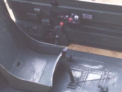
Gun sights
The gun sight is
often one of the most prominent additions to a cockpit interior, but is one area
that is often neglected. The main problem that I have seen over the years is
that most people don’t realize just how large these items were, and end up
producing a great piece of detail, but at around 2/3 the size it should be.
Books are available on this subject, but the best option to understand just what
is required is a trip to a museum. If you are lucky enough to be able to get to
sit in a WWII fighter, you will soon see that the gun sight fills your forward
field of vision, very little can be seen through the front, you’ll have to look
round the gun sight so see anything!
Having worked out
your dimensions, the next step is to work out just where to start, as most
sights were quite complex shapes. My advice would be to try and break the sight
down into simpler component shapes/blocks, rather than looking at it as a whole.
If you do this, you will soon see that the sight can be made up of much simpler
blocks, tubular sections, bits of litho and plasticard, lengths of wire etc…
A very useful
material that I have used in the past is a solid resin industrial model making
material. This material is know by many names, but Model Board, Model Lab, Pro
lab and Chemi-wood are 4 of the most common. This material is a hard resin based
block; it has no grain, and is easily worked by hand or on machine tools. You
can drill, tap, file, turn etc…it with ease, and is bonded easily with cyano.
Being quite dense, it requires no special surface treatment prior to painting.
It is a little heavy in large pieces, but in small amounts ( gun sights etc… )
it is ideal.
Contact Amber
Composites to source this material (
www.ambercomposites.co.uk )
Additional detail
With any cockpit,
the dashboard and gun sight ( if it has one ) are going to be the most visible
parts. If you choose to go further than this, adding detail to the cockpit walls
and floor, the same materials and techniques as used for the gun site can be
used.
|
Remember
to always break each component down into its simplest form. Another
tip is don’t always rely on making everything yourself, it’s amazing
sometimes what you can find kicking around the corners of your bench
that can be used. The conical and tubular tops of old cyano bottles
can be cut down and reworked, often ideal for gun sight parts. A
small piece of old fuel tube, spiral wrapped in soft solder can make
a good representation of the flexible oxygen tube when painted matt
black. |
 |
My final tip is one
of adhesives. After spending around 4 months detailing the cockpit of my 1:6
scale P-51D ‘Frenesi’, the first time I ran the engine, several parts of the
cockpit parted company with the sidewalls, and were left rolling around on the
floor! Why, because I had used the wrong adhesive to mount these parts. Because
of the size and weight of certain parts ( gun sight, throttle quadrant etc… )
they soon started to vibrate, and the cyano / litho plate joint simply
fractured. Ideally, you need to ‘soft mount’ any of the larger parts to help
insulate them from the engine vibration. Clear RTV silicone is good for this,
but the best I have come across is ZAP’s Zap A Dap A Goo 2, this clear adhesive
will stick pretty much anything to anything, and dries very slightly flexible. I
used this to reattach the parts in the P-51 cockpit…2 years later, they are
still there!