Getting started in CNC…
for the R/C Modeler
By Richard Wildey
Revision 5
September 12, 2006
Email: pilotjunky@hotmail.com
Welcome to CNC Session #1
– Introduction and getting started.
 The
purpose of this article is to discuss CNC (http://en.wikipedia.org/wiki/CNC)
as it applies to building Remote Control Aircraft. I will not discuss CNC
beyond the level of detail necessary to be happily cutting parts out of whatever
material you choose.
The
purpose of this article is to discuss CNC (http://en.wikipedia.org/wiki/CNC)
as it applies to building Remote Control Aircraft. I will not discuss CNC
beyond the level of detail necessary to be happily cutting parts out of whatever
material you choose.
CNC, GCode (http://en.wikipedia.org/wiki/G-code), and Machining are a fantastic skills which you are welcome to take to any level, but the purpose of this thread will be to help you get started. Hopefully this thread will allow you to avoid some of the pitfalls I’ve experienced in my almost two years since “stumbling” across CNC. I am not a machinist, I am not particularly skilled with tools, I have no idea how to work with metals, and until this project I had never used a soldering iron. My only real skill is with computers, but to tell you the truth, that’s a small piece of the CNC process.
 So,
with that said, I’m going to start from the ground up, just like I did. I’ll
assume you have nothing except the idea and a little ambition. I’m going to
take you through the process of building a CNC machine, all the way to cutting
out your first wing rib. Along the way I’ll introduce you to various sources on
the internet. In several cases, I’ll refer you to the documents included with
various internet purchases. I’m not so much teaching you “how”, but rather I am
teaching you “where” to get the information. I’ll go on to explain a little
about the electronics for the CNC machine as well as how to hook up the unit to
your computer. I’ll move on to introduce you to a few pieces of software,
several of which are free. Ultimately we will bring it all together by taking a
part from a paper plan and having the machine cut it out for us. I’ll also
mention several pieces of software along the way with which I have experimented…
some good, some not… but I’ll point them out and ultimately let you decide. The
sky is the limit after that.
So,
with that said, I’m going to start from the ground up, just like I did. I’ll
assume you have nothing except the idea and a little ambition. I’m going to
take you through the process of building a CNC machine, all the way to cutting
out your first wing rib. Along the way I’ll introduce you to various sources on
the internet. In several cases, I’ll refer you to the documents included with
various internet purchases. I’m not so much teaching you “how”, but rather I am
teaching you “where” to get the information. I’ll go on to explain a little
about the electronics for the CNC machine as well as how to hook up the unit to
your computer. I’ll move on to introduce you to a few pieces of software,
several of which are free. Ultimately we will bring it all together by taking a
part from a paper plan and having the machine cut it out for us. I’ll also
mention several pieces of software along the way with which I have experimented…
some good, some not… but I’ll point them out and ultimately let you decide. The
sky is the limit after that.
As a side note, there is not a single component of this CNC project, (except for the wood and a few Home Depot screws) that wasn’t ordered over the internet and shipped to my door. I will be pointing out dozens of web addresses full of information which will get you going. The internet and a credit card will be essential to your success.
This project isn’t free. I’ve probably invested (note: “invested”) somewhere between $1,000 and $1,500 in hardware and software for this project. I suppose you could do it for under $1,000, but you’d have to get many things right the first try, and make some compromises in terms of software. All in all, it was an inexpensive project relative to buying an “Off the shelf” model. As an additional note, I’m not associated with any of the company’s, products or people I’m going to mention. In fact, I’ve never spoken to most of them except through e-mail and internet forums… oh yeah, you better get used to spending time on internet forums, just like RCSB because it’s where I’ve learned a great deal.
I guess I should also point out, as blindingly obvious as it may be, you will need a computer for this project. In particular, you need a computer with a “standard” or “typical” parallel port. Don’t get fancy here, no USB adapters. The power of the computer can range from an old DOS machine (for those of you old enough to remember DOS) to a modern Windows XP computer. However, there are compromises and challenges in both environments which we will discuss later on. Start to think about where you are going to source this computer now. Some offices have old DOS computers for free, whereas a more modern computer can be ordered from Dell or Tigerdirect.com as an example. Heck, you may already have a computer you could use for this but keep in mind it needs to be relatively close to the CNC machine wherever that may end up. My point is the computer is going to get pretty dusty. More on the computer “stuff” later, but you’re going to need one.
Let’s start with a little history…In January 2005, I decided I’d had enough of cutting material (Balsa) using an Exacto knife, or Lite Ply using the scroll saw. I figured there must be a better, more accurate way of building. My research, trials and tribulations led me to a machine and some processes which will likely be with me forever. I investigated laser cutting (http://www.ulsinc.com/english/index.html), but it was cost prohibitive, and seemed a little dangerous. I don’t believe lasers can do 3D shapes either (not that I’m going to discuss that here). I looked at “buying” a machine, but that was a little pricey too (Check out http://www.k2cnc.com). Ultimately, my price range lead me to a wooden CNC machine from http://www.hobbycnc.com . My workshop will never be without a CNC machine now. The discussion of both the CNC machine, and the electronics will be based on the HobbyCNC machine. Go to that web site, take a look, poke around and we will get started with the project in the next addition to the thread.
Welcome to CNC session #2 – Building the Machine
 In
this session I hope to discuss a few things regarding the CNC machine itself.
The instructions you will purchase are very clear, so I’ll focus on odds and
ends outside of the “real-world” of building the machine.
In
this session I hope to discuss a few things regarding the CNC machine itself.
The instructions you will purchase are very clear, so I’ll focus on odds and
ends outside of the “real-world” of building the machine.
Start by going to http://www.hobbycnc.com and purchasing the plans. It will be the best $25 you’ve ever spent. Once you have purchased the plans, Dave (from HobbyCNC), he will give you access to his Yahoo support group. I highly recommend you join and start reading through the threads. I’ll assume we are going to build the machine first (the wooden parts), then order the electronics later on. The manual supplied contains a good parts list (bill of materials) and even includes part numbers.
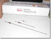 The
biggest single expense on the machine is the lead screws from Kerk Motion (http://www.kerkmotion.com).
If you go to their web site to get their phone number and call them, you can
simply tell them you want the “HobbyCNC kit” and they will know exactly what to
send you. I’ve read many posts on people trying to build their own lead screws
to save money. I’d recommend against it as the lead screw “nut” plays a huge
roll in ensuring accuracy, and that your machine doesn’t tear itself apart if
you accidentally hit a limit. The nut seems to act as a “clutch” of sorts. The
Lead Screws are precision parts, and as you will see later on, there are some
basic mathematics required in using the lead screws. Do yourself a favor and
buy the Kerk Motion lead screws. Maybe for your second machine you can
experiment a little.
J
The
biggest single expense on the machine is the lead screws from Kerk Motion (http://www.kerkmotion.com).
If you go to their web site to get their phone number and call them, you can
simply tell them you want the “HobbyCNC kit” and they will know exactly what to
send you. I’ve read many posts on people trying to build their own lead screws
to save money. I’d recommend against it as the lead screw “nut” plays a huge
roll in ensuring accuracy, and that your machine doesn’t tear itself apart if
you accidentally hit a limit. The nut seems to act as a “clutch” of sorts. The
Lead Screws are precision parts, and as you will see later on, there are some
basic mathematics required in using the lead screws. Do yourself a favor and
buy the Kerk Motion lead screws. Maybe for your second machine you can
experiment a little.
J
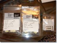 The
next pieces are the drill rod and bushings. The bushings are from Igus,
http://www.igus.com. Again, from experience it is easier to get their phone
number off of the web site and call them to tell them the part numbers you
need. The gantry moves on something called Drill Rod. This drill rod is
highly polished and is particularly difficult to cut. So a key point is to be
sure you don’t buy “just any” drill rod from Home Depot, buy the good drill rod
from somewhere like MSC (http://www1.mscdirect.com/CGI/N2DRVSH?PMSECT=750)
for example. It’s heavy and shipping will cost a fair bit, but it’s worth it.
The
next pieces are the drill rod and bushings. The bushings are from Igus,
http://www.igus.com. Again, from experience it is easier to get their phone
number off of the web site and call them to tell them the part numbers you
need. The gantry moves on something called Drill Rod. This drill rod is
highly polished and is particularly difficult to cut. So a key point is to be
sure you don’t buy “just any” drill rod from Home Depot, buy the good drill rod
from somewhere like MSC (http://www1.mscdirect.com/CGI/N2DRVSH?PMSECT=750)
for example. It’s heavy and shipping will cost a fair bit, but it’s worth it.
Mistakes I made along the way which you should avoid…
 Remember
to always watch the clearance between the bottom of the Gantry and the top
of the cutting surface. This will maximize the thickness of the material
you can cut. I inadvertently forgot to cut the Z Axis lead screw to
maximize the space, so keep an eye on it. If it’s too long at the bottom,
it gets in the way of the material passing under it.
Remember
to always watch the clearance between the bottom of the Gantry and the top
of the cutting surface. This will maximize the thickness of the material
you can cut. I inadvertently forgot to cut the Z Axis lead screw to
maximize the space, so keep an eye on it. If it’s too long at the bottom,
it gets in the way of the material passing under it.

I’m hoping that with the tips above, combined with the very clear manual that comes from HobbyCNC to build the machine, you will be well on your way to CNC success. In the next session we will take a look at the Control Unit.
Welcome to Session #3 – Building the 3 Axis Control Unit
 Let’s
take a look at building the three axis control unit, again from HobbyCNC (http://www.hobbycnc.com).
I recommend you purchase one of the packages from HobbyCNC which includes the
control unit, and three stepper motors. I also recommend the 127oz steppers as
they are more than powerful enough for this machine. I’ve read the 200oz
steppers are a bit much for this particular machine. I actually use the 80oz
steppers, I didn’t know any better at the time, but to tell you the truth, they
work just fine.
Let’s
take a look at building the three axis control unit, again from HobbyCNC (http://www.hobbycnc.com).
I recommend you purchase one of the packages from HobbyCNC which includes the
control unit, and three stepper motors. I also recommend the 127oz steppers as
they are more than powerful enough for this machine. I’ve read the 200oz
steppers are a bit much for this particular machine. I actually use the 80oz
steppers, I didn’t know any better at the time, but to tell you the truth, they
work just fine.
The only other things you will need to purchase are
I’ve read endlessly on the HobbyCNC forum people who don’t know what they are doing, and are trying to adapt existing power supply’s to make their machines work. You know what, use the ones recommended.
Most recently, Dave from HobbyCNC has come out with the “Pro” board. This is the one you want to get. It’s inexpensive and has some great features such as it automatically powers down the steppers after a certain amount of time.
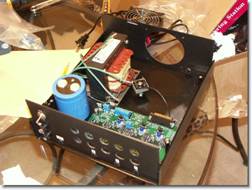
It’s time to build the control unit. What will arrive at your door is a small box from USPS and a bunch of electronic parts that look daunting at first. Fear not. I had never soldered a PCB in my life. Oh, PCB is Printed Circuit Board, I learned that along the way also. The instructions from HobbyCNC are extremely well laid out, and if you follow them carefully you will have it together and tested in a couple hours. DO NOT SKIP STEPS on the HobbyCNC instructions… they are in a critical order.
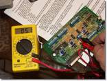 I
will admit I had to go out and buy a few tools for the job. A voltage meter, a
soldering Iron, the proper solder, a small de-soldering pump, and some flux.
Your local Radio Shack will carry all of these. I’m sure they can be sourced
online also. As you can see in the picture, you will need a voltage meter to
test for the correct voltage limits BEFORE installing the logic chips.
I
will admit I had to go out and buy a few tools for the job. A voltage meter, a
soldering Iron, the proper solder, a small de-soldering pump, and some flux.
Your local Radio Shack will carry all of these. I’m sure they can be sourced
online also. As you can see in the picture, you will need a voltage meter to
test for the correct voltage limits BEFORE installing the logic chips.
One important note! Some of the parts are important in terms of how they are placed in the PCB. Direction matters, so pay attention to the direction as you are soldering. I made the mistake at least once of having to remove, and potentially reorder a part to because it couldn’t be removed cleanly.
The key throughout this is to FOLLOW AND READ THE INSTRUCTIONS carefully. They are extremely well laid out. If you are confused at any point, go ahead and ask on the Yahoo forum as the support from the group is fantastic.
Session #4 – Hooking the machine up to a computer (1)
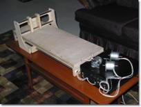
By this point I’m going to guess you are several weeks into your project. By following the HobbyCNC instructions carefully, you managed to build your CNC machine, and you have the control unit built and all plugged into the CNC machine. But there it sits, dusty and quiet. This is where that computer begins to come in which I discussed in session #1. Hopefully you’ve found either an old computer capable of running DOS, or you have an extra, more modern computer which is capable of running Windows XP. I’m also going to have to assume you know some computer basics. If you are reading this article on the computer, chances are you have enough computer literacy.
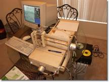
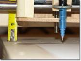
 If
you don’t own a Dremel, perfect. Don’t run out and buy one for this project
just yet. If you’ve got it in the machine… take it out. It’s time to plug the
control unit into the computer and continue learning. Now is NOT the time to be
worrying about a bit in a Dremel tool spinning around. I recommend building a
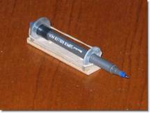
test unit which utilizes a pen. That’s right; replace the Dremel with a pen for
now. I built a simple pen holder with a small piece of wood, two washers and a
rubber band to hold the pen down. I screwed that entire unit where the Dremel
will eventually live. There are several reasons, the most important is safety,
but secondly, you are much less likely to have the machine tear itself apart
when using a pen versus a Dremel. My first successes with the HobbyCNC machine
were with a pen, not a Dremel as you can see from these pictures. In many
respects, you have built yourself a rudimentary plotter for your computer. So
as you begin to test and learn, have some success drawing parts and eventually
you will have much more success cutting. For now, no need for the dust.
If
you don’t own a Dremel, perfect. Don’t run out and buy one for this project
just yet. If you’ve got it in the machine… take it out. It’s time to plug the
control unit into the computer and continue learning. Now is NOT the time to be
worrying about a bit in a Dremel tool spinning around. I recommend building a
test unit which utilizes a pen. That’s right; replace the Dremel with a pen for
now. I built a simple pen holder with a small piece of wood, two washers and a
rubber band to hold the pen down. I screwed that entire unit where the Dremel
will eventually live. There are several reasons, the most important is safety,
but secondly, you are much less likely to have the machine tear itself apart
when using a pen versus a Dremel. My first successes with the HobbyCNC machine
were with a pen, not a Dremel as you can see from these pictures. In many
respects, you have built yourself a rudimentary plotter for your computer. So
as you begin to test and learn, have some success drawing parts and eventually
you will have much more success cutting. For now, no need for the dust.
So, now comes the big moment. Be patient there as the marriage of mechanical components to the computer takes some “figuring out”. I remember as I posted on the HobbyCNC forums, one fellow told me this piece is a “right of passage” in the HobbyCNC world. I’ll try to hold your hand.
The HobbyCNC machine plugs into the Parallel port on your computer. Don’t use any sort of fancy adapters, don’t use USB connectors, use the parallel port that should already be on your computer. The PCB you built communicates strictly through this port.
Earlier I had mentioned you need to decide whether you are going to be running a DOS based computer or a Windows XP based computer. Here are some of the reasons you would go one way or the other, and hopefully this will guide you in making your decision. Ultimately though, your comfort level will help make the decision.
The advantages of a DOS based machine are that they are cheaper, and the software to run on the computer from DakEng (http://www.dakeng.com/turbo.html) is also free. Even the DXF to GCode converter is free. It is called ACE and is also available from DakEng at (http://www.dakeng.com/ace.html). Outside of cost, this software if very robust and is well supported. There are hundreds of users, and lots of forums on the internet to meet other people. In fact, I started out with TurboCNC, and an old DOS machine which I built from an old computer laying around the office. I did learn a ton here, and it was what made the first drawings and cuts with my CNC Machine.
The negatives of the DOS machine are they it is not easily networked, and pretty much guarantees that you will have to have multiple computers since you are likely using a Windows based program such as AutoCAD or Corel Draw or other similar programs to create your drawings for cutting. This flipping between computers was ultimately what led me to search for a Windows solution such that I could easily network the computers and have AutoCad files converted to GCode on the same computer. I now do my AutoCAD work in my office along with convert and test my Gcode. Then, through my wireless network at home I transfer it to the Windows XP machine in the workshop for cutting.
My first move away from DOS was a hybrid. I began to use a Windows program called KellyCAM to drive my control unit. (http://www.kellyware.com/kcam/). Kelly cam is not free, and was a hybrid because I still used ACE, a free Windows program to convert my DXF files to GCode that the machine could understand. KellyCAM served me well, but it still wasn’t enough for me.
You may at this point be wondering why not use the DOS compatibility in Windows XP to run TurboCNC and ACE… problem solved right? Well, no. The CNC machines are very timing sensitive. That means they need complete control over the parallel port, and Windows XP DOS boxes do not allow for direct control over the parallel port. Window simply isn’t designed that way, and it simply is not going to work.
Ultimately, I decided to move to a Windows XP machine. My research led me to http://www.artofcnc.ca or http://www.machsupport.com. There you will find a product called Mach3. Mach is a Windows Based CAM software which has a “driver” specifically written for Windows that takes over control of the Parallel port. Mach has also recently implemented a program called “LazyCAM” which allows DXF files (and others) to be converted to GCode. At the time of this writing, Mach was $159. This software is a fantastic deal. Art Fenerty at CNC is the author of the product and has superb support on the web site and several forums found at his web site. Take a look, download the manuals and start reading. There are also excellent educational videos available for FREE on his web site. In fact, you can download the entire software package and try it out. The ONLY limitation of the free software is that it will only generate 150 lines of G-Code.
To take it to another level, your next several hours should be spent understanding Mach and reading the documentation. Even if you plan on later using a DOS machine I would suggest you take a look at (http://www.artofcnc.ca)
You’ll notice you still haven’t turned on your CNC unit yet. We are getting there but there is much work to be done in the software yet. Much of your learning can take place in “simulation” mode using Mach3. I’m going to assume from here on that you are using Windows and Mach3 for your machine. However, many of the concepts we will be discussing still apply in a general sense.
Before we conclude this session, let’s take a look at some basic mathematics as it relates to the CNC machine. One piece of configuration in the software is where we calculate how to make the hardware component move a “unit” when we tell it to move a “unit”. For example, how does the software know to move the hardware one “inch”.
Let’s take a quick look at setting Turns Per Inch (TPI). You will recall in an earlier session I discussed the Lead Screws and that there would be some math with respect to them. Well now is the time to consider just that. This is not complicated, so read slowly.
Each stepper motor turns 1.8 Degrees per step by design. Since we know from school there is 360 degrees in a circle, we can calculate that our steppers will take 200 steps to turn 360 degrees. (360/1.8) = 200
Each lead screw will have a specific TPI associated with them. In the case of the Kerk Motion screws, the Z Axis is 32 TPI and the X, Y Axis are 10 TPI. Combining the information from the steppers of 200 steps for a full turn, and the information that the X and Y Axis lead screws require 10 turns to move an inch, we can easily calculate that 10 turns times 200 steps for a full turn is 2000 steps to make the X and Y Axis move one inch. Using the same math, we can calculate that the Z Axis will take 32 x 200 = 6400 steps to make the machine move one inch.
This simple math will be used to configure the Mach software in the next session.
Session #5 – Detailed Software Options for controlling the machine – Your first jogs.
The concepts I discuss in this section will apply in a general sense to any software you use to control your unit. In this particular case I’m going to assume you are using Mach3. It’s free to try and its Windows based. As I said in an earlier piece, the first “jogs” are a right-of-passage in Hobby CNC.
A “jog” of the machine is reference to moving the axis by holding down a particular key on the keyboard. Generally speaking the “arrow” keys will move the gantry in the X and Y Axis, while a key combination such as “Page Up” or “Page Down” will jog the Z Axis. There are several purposes to jogging such as moving the gantry to the 0,0 coordinate before you begin cutting. Or, if you have completed a series of cuts, you can manually jog to move the cutting tool out of the way. In this case we are going to look at some ways to make the machine jog; just to be sure we have the software configured.
With your computer up and running, and the control unit plugged into the parallel port of the computer, let’s go ahead and turn on the control unit. Make sure there is no tool in the gantry. The Dremel will just get in the way, as will the pen at this stage. The Stepper motors tend to “Hiss” which is normal, and keep in mind they are designed to get very hot over time. No idea why, but I’ve come to learn this is normal.
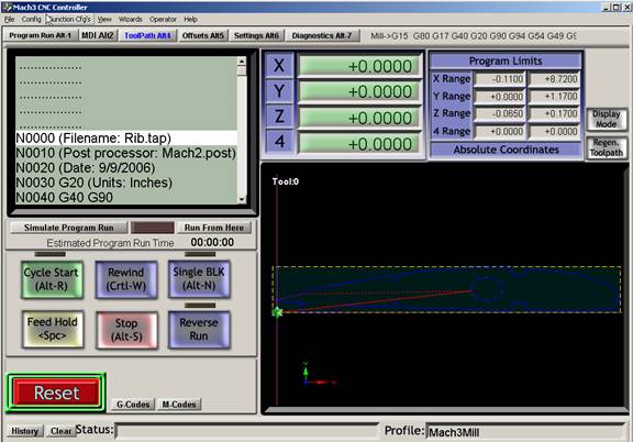
 I’m
going to also assume you have been to the Mach3 web site,
http://www.artofcnc.ca, downloaded and installed the program per the
instruction. With that said, start the software by double clicking the MachMill
icon. The primary screen should come up as on the left. I won’t go into any
description of the screen just yet, but suffice it to say you are about to spend
some time configuring the software. From the top, you will be selecting, Config/Ports
and Pins and then Config/Motor tuning. By only focusing on these areas of set
up , you will soon be able to “jog” your machine and see the three components
finally move into action. The Wooden machine, the Control Unit and the Computer
software will all work together to breathe life into the CNC machine as a whole.
I’m
going to also assume you have been to the Mach3 web site,
http://www.artofcnc.ca, downloaded and installed the program per the
instruction. With that said, start the software by double clicking the MachMill
icon. The primary screen should come up as on the left. I won’t go into any
description of the screen just yet, but suffice it to say you are about to spend
some time configuring the software. From the top, you will be selecting, Config/Ports
and Pins and then Config/Motor tuning. By only focusing on these areas of set
up , you will soon be able to “jog” your machine and see the three components
finally move into action. The Wooden machine, the Control Unit and the Computer
software will all work together to breathe life into the CNC machine as a whole.
 The
first piece of configuration is the “Ports and Pins”. There is a pin on the
parallel port for movement, and another pin for direction. These are clearly
defined in the HobbyCNC manual for the PCB you put together earlier. Getting
these pins set up correctly in the software is key.
The
first piece of configuration is the “Ports and Pins”. There is a pin on the
parallel port for movement, and another pin for direction. These are clearly
defined in the HobbyCNC manual for the PCB you put together earlier. Getting
these pins set up correctly in the software is key.
After the pins are configured, you will have to use the information on TPI from Session 4 to configure the steps.
There is great news with respect to setting up these elements. There is a video on the http://www.machsupport.com web site which describes how to set these up. I would strongly recommend you watch all of them. I have several times and learned a little something from each on.
A point to be made here is that in CNC and in the Mach and TurboCNC software there are hundreds of features. In order to accomplish what we are attempting to achieve as aero modelers, only a small portion of them are required. Keep that in mind. You do not need to know everything about the software to have a great time using CNC. You will hear terms such as backlash and spindle speed, but to tell you the truth, my CNC airplanes have flown perfectly, and I don’t even know what those terms mean!
Having set up your ports and pins, and set the TPI or “Steps Per” in Mach, you are getting close to ready to start jogging. Somewhat unique to Mach3 is the ability to control the acceleration and velocity of you motors. In the same screen where you set the “Steps Per” or TPI, start with a low velocity and acceleration and as you begin to jog the machine, you will figure out what is best for your machine setup.
The Control Unit should now be on, plugged into the parallel port of you computer which is on, and running Mach3. You’ve watched the videos, you’ve configured the Ports and Pins, and you have configured the “Steps Per” and things are ready to go.
A couple final Notes. This is a machine. It really has no brain. It doesn’t know the difference between a piece of wood and your finger, so BE CAREFUL. Also, the machine is quite willing to tear itself apart. If you jog beyond the ends, the machine will make every effort to keep going, likely doing some damage along the way. Lastly, take a close look at the machine and make sure nothing is touching, the Dremel nor pen is in the unit. All of these things can quickly destroy a lot of fun.
Now is the time. Tap an Arrow key. Did anything happen? Hopefully it did, even if the sound changed on one of your steppers, it means they are communicating. Typically, the problem is in the software configuration. Go back and recheck your ports and pin setup. It is typically where things go wrong. If you think you have it right, then flip the numbers around to something you think may be incorrect. The point is, try moving the numbers in the ports and pins until something begins to move. If it does start moving, check the directions, and so on. Eventually, as you jog you will get the direction, the speeds, and the axis all tuned correctly.
If you are using TurboCNC, as I did to begin with, the exact same challenges applied. Check, check, and recheck those port and pin configurations.
So, with any luck, you jogged. The machine moved with the commands from the computer. It’s quite satisfying so stick with it. Now onward to actually drawing something with the machine.
Your skills will soon advance once you have figured out how to jog the machine. Jogging is the first step to understanding your machines movement.
Session #6 – Raster to Vector - Converting a JPG/TIFF to a DXF file.
It’s time to start contemplating our first parts. As I mentioned in the first session, let’s focus on a Wing Rib. Since many of the plans we get are paper based I’m going to assume that is the case here also. I have developed several techniques for scanning and scaling large plans. Kinkos is a great place to scan some of the largest plans to get them into a digital format. Once they are digital you can begin to select pieces for cleanup and cutting.
I suggest you download a couple of tools. One is called IrfanView (www.irfanview.com) and is a free tool for manipulating images. Often an image will need to be reduced in color or rescaled; this is a great tool.
Secondly, download WinTopo (http://www.wintopo.com). There is a free version of their program up their, and it is excellent for converting JPG to TIFF format to a Vectorized drawing such as DXF format for CAD.
CAD is not the only means by which to manipulate drawing for cutting. Corel Draw and other formats are supported as well. My preference is CAD as it allows me to manipulate drawings in a measurable and accurate way. I use AutoCAD but there are free CAD packages online such as from (http://www.a9tech.com/)
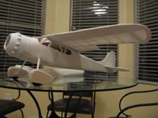
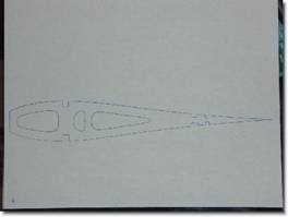
Having said all of that, let’s start by scanning in a paper plan. In this example I’ll use one from the August 2006 copy of FlyRC Magazine. If it’s worth any sort of CNC inspiration, that entire plan was manipulated using the methods I am describing and eventually has turned into the Cessna195 you see pictured on my kitchen table below.
I have taken the liberty of cropping Rib W3 from the plans above, and you can see in the pictures below I have rotated it. As with most things, there is more than one way to get a job done. For example, you may want to use your favorite “Paint” program to clean up the JPG scan, or you may want to convert the “dirty” picture to DXF format and clean it up in your CAD program later. In this example, I will use Microsoft Paint to clean up the Rib. One thing to keep in mind here is that you are setting up a “Cutting Path” so some lines will be removed for that purpose.
Figure 1. Cropped from original Scan and rotated using Irfanview
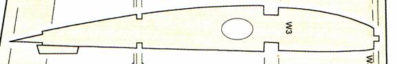
Figure 2. Colors reduced to two by Irfanview
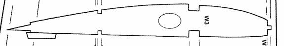
Figure 3. Lines cleaned up using Microsoft Paint.
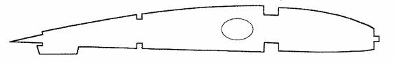
Figure 4. The part has been run through WinTopo and Vectorized (Turned into a DXF CAD file) and is now ready for final cleanup in CAD if necessary.
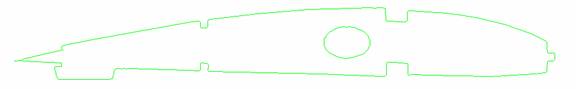
Figure 5. Is getting a little ahead of ourselves, but it shows you the part in the CAM (Computer Aided Manufacturing) software which we will discuss later. Mach3 has LazyCAM as I mentioned, in this case I use Sheetcam (http://www.sheetcam.com)
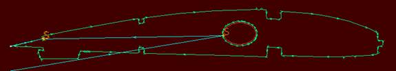
Figure 6. And finally below is the wing Rib in the CAM software, Mach3 ready to tell your CNC machine how to cut the part.
Although the process may look somewhat daunting, it really isn’t once you’ve become proficient with the software tools. In fact the pictures above took only a minute or two to produce from scratch in the various pieces of software.
One concept worth mentioning before we close out this section is “Scale”. There are several ways to handle this, but the one I use has proven the simplest of many. When a paper plan is scanned into the computer, it is scanned at a DPI (Dots Per Inch). This is important because if the paper plan was 1:1 you will have to set the scale 1:1 in WinTopo when converting the JPG into a DXF file. If you are scanning a plan from a magazine for example, chances are the scale is much smaller than the plan actually intended. The Cessna195 above for example was to be increase 250%. So, I scanned in my plans at 250% and noted the DPI of the JPG. Then when bringing the picture into WinTopo, I set the DPI to ensure the scale is correct in CAD. This ensures that the parts to eventually be cut are the correct dimensions.
The scale could be handled in the CAD program, or even in the Mach3 program itself. You will eventually learn the approach that works best for you. It is an important concept however, and some practice may be required.
Session #7 – Converting a DXF to GCode for use in the Machine
The final step is converting the drawing into something the Control Unit can understand. This is called “GCode”. GCode is a standard set of commands which the software interprets to put the appropriate pulses out through the parallel port to make the machine move. GCode is created from several formats, the most common is DXF so that’s what I’ll assume you are using. If you are using Corel Draw for example, it is possible for some of these CAM tools to take HPGL or another format into GCode, but I prefer DXF just because that’s my comfort level.
In session six, we got a little ahead of ourselves. So let’s backtrack a bit and discuss some important concepts.
First, let’s discuss “Offset”. The bit at the end of a Dremel has a diameter and can greatly affect the end result of your parts. The machine will cut down the center of you line, and without taking the radius of the cutting bit into account, the size of your part will be off by that dimension. There are a few ways to handle this. Again, assuming you are using a CAD package, you can create the offsets using the offset feature in CAD. This works but you need to keep a few things in mind. First, there are outside offsets and there are inside offsets. In our Rib example from session six, the inner circle cut requires an inside offset, and the outline of the part requires an outer offset. The offset is typically the radius of the bit you are using, or larger if you want to leave some finishing area on your part.
The next important concept to keep in mind is “Layers”. Layering is a CAD concept which allows parts, or pieces of parts to be separated. In terms of GCode conversion this is vital and the reason is simple. Again, using our Rib as an example, if you cut the outline of the rib out first, the piece of material will drop out before it has a chance to cut out the inside pieces. In CAD you would create separate layers for cutting and explicitly tell the GCode converter which layers to cut first.
After offsetting and layering an entire plan, you will soon begin to wonder if there is a “better way” and the answer is, yes if you are using LazyCAM in Mach, or SheetCAM which I will discuss here. If you are using a free program such as ACE, it has a very limited ability to perform any offsetting or ordering the cuts. It relies on your ability to set these entire cuts up in your CAD program.
I started by using ACE as I had mentioned but soon realized that to make any quick progress I needed something more sophisticated. Mach3 has included LazyCAM and I encourage you to go to http://www.machsupport.com and look at the video describing LazyCAM. It takes care of many of the Offset and ordering issues we discussed.
A step beyond LazyCAM is SheetCAM. Sheetcam is written by a fellow named Les in the UK. (http://www.sheetcam.com). He seems to have excellent support and I have grown to really like his program. The Rib above with the red background is a screen shot created from SheetCAM. SheetCAM is more sophisticated and relieves the stress of offsets, cutting order, starting positions completely. One fantastic feature of SheetCAM is that there is a tool to allow you to create TABS on parts. If you have ever purchased a model kit, you will notice that all of the pieces are held in the wood, and you have to break them away from little TABS. Well, this is what SheetCAM can help you do. This Tab function is important for a few reasons. First, it allows you to use every square inch of you material by organizing the parts for cutting. Second, it allows the wooden piece to maintain structural integrity as the parts are cut, and finally it keeps pieces from “popping” out and getting in the way. Effectively you will be able to model your own sheets, just like the guys at Great Planes do.
SheetCAM has some other time saving features. It understands the dimensional space within which it is operating. It understands the machines dimensions, the cutting area dimensions, and the material dimensions. This is all important such that SheetCAM can tell you when you are at risk of going outside of the material, or most importantly when you are at risk of hitting your cutting bed. Going too deep on the Z AXIS is probably the one area where you are most like to screw up as you learn. Be very, very careful in this regard.
With all of that said, SheetCAM is $150 (approx), LazyCAM comes with Mach3 for the $159, and ACE is free. They will all have their quirks. If I had to do it all over again, I would probably start with LazyCAM and move to a product like SheetCAM as I became comfortable with the concepts.
Session #8 – Drawing your first parts…. That’s right, drawing, not cutting.
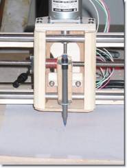
 It’s
time to try and bring everything I have discussed together and draw your first
parts. As you can see from the pictures, I decided that attaching a pen to the
CNC machine was the best approach to learn. This left zero chance of hurting
myself or the machine. It was made from a scrap of wood, two washers and a
rubber band. I have to give credit where it’s due and say this simple design
was my fathers, and that it worked very well. I think the pictures speak for
themselves from a design and results perspective. I urge you to take this
approach in testing and learning your machine. Even after hours with the pen I
still managed to damage my cutting surface the first time I introduced the
Dremel. Nothing major, but the scar is still on the machineJ.
It’s
time to try and bring everything I have discussed together and draw your first
parts. As you can see from the pictures, I decided that attaching a pen to the
CNC machine was the best approach to learn. This left zero chance of hurting
myself or the machine. It was made from a scrap of wood, two washers and a
rubber band. I have to give credit where it’s due and say this simple design
was my fathers, and that it worked very well. I think the pictures speak for
themselves from a design and results perspective. I urge you to take this
approach in testing and learning your machine. Even after hours with the pen I
still managed to damage my cutting surface the first time I introduced the
Dremel. Nothing major, but the scar is still on the machineJ.
I’m making a couple assumptions here. One is that whatever software you are using to drive the machine (TurboCNC or Mach3) you have practiced jogging, and that when you jog the machine an inch it actually moves an inch. We need to be sure the scaling is correct. The second assumption is that you know where your emergency stop button is on your computer. It’s usually the ESC or escape key. This will be vital if you see the machine going crazy on you or getting near an edge.
 The
GCode you create with ACE, SheetCam or LazyCAM should now be loaded into your
machines software. I’ll assume you are using Mach3 here. When you load the
GCode, you should see something like the picture to the left. One of the
beautiful things is that Mach will show you what you are cutting graphically.
In Mach you can also see a few important things. There are something called
DRO’s or Digital Read-Outs. These digital readouts represent the movement of
the three Axis. If an Axis is moving, the appropriate DRO’s are moving and
indicating where they are relative to what you assigned as as the 0,0,0
coordinates. Take a look at those.
The
GCode you create with ACE, SheetCam or LazyCAM should now be loaded into your
machines software. I’ll assume you are using Mach3 here. When you load the
GCode, you should see something like the picture to the left. One of the
beautiful things is that Mach will show you what you are cutting graphically.
In Mach you can also see a few important things. There are something called
DRO’s or Digital Read-Outs. These digital readouts represent the movement of
the three Axis. If an Axis is moving, the appropriate DRO’s are moving and
indicating where they are relative to what you assigned as as the 0,0,0
coordinates. Take a look at those.
When the GCode loads, you are going to want to Jog the machine to the X Axis 0 and the Y Axis 0 point. In this case, the 0,0 point can be the bottom left corner of the piece of paper you have put on the machine to draw with. All GCode moves will be relative to this 0,0 point. Again, there are some excellent Videos discussing this concept at www.machsupport.com. They apply whether you are using Mach, TurboCNC or whatever software to drive your machine. In my opinion, the biggest challenge was understanding the Z Axis. When you are drawing parts using the pen, the Z Axis is really either up, or it’s down. You still need to watch it carefully as this is your chance to learn. As the Z Axis moves, watch how far it goes, and consider what you would do if there was a piece of material there instead of a pen. In many cases you will be happy it’s just a pen. The Z Axis movement is at maximum only a couple inches, but it’s vital to success.
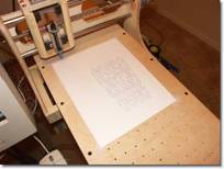
 Your
Gcode is loaded, you’ve checked your Z Axis movement, the machine jogs
correctly, and everything seems in order. It’s time to execute the GCode. In
Mach you can click the big Run button and the system will begin to interpret
your GCode and translate it into pulses through the parallel port to the
machine. With any luck you will begin to see a beautiful Rib be drawn on you
paper such as this one, my very first, in the picture.
Your
Gcode is loaded, you’ve checked your Z Axis movement, the machine jogs
correctly, and everything seems in order. It’s time to execute the GCode. In
Mach you can click the big Run button and the system will begin to interpret
your GCode and translate it into pulses through the parallel port to the
machine. With any luck you will begin to see a beautiful Rib be drawn on you
paper such as this one, my very first, in the picture.
Chances are something has gone wrong. It’s probably your scaling, or your Z Axis tried to descend too far, or your pen went to the left instead of the right which would be a directional issue. In any case, they are all resolvable issues and you will be very glad you used a pen and not a Dremel at this stage in the game.
You are likely going to have to go back and take a look at your configuration settings in the software you are using, or you are going to have to check the tool you used to generate your GCode. Scaling is an issue you need to pay attention to. As you go from a picture to GCode, it needs to know that something is an inch, not a foot long.
Once your drawing is correct, now it’s time to contemplate attaching the Dremel tool in the next session.
Session #9 – Cutting your first parts.
I can’t stress enough how important safety is here. Please take your time. The Dremel is probably the safest of any router, but the machine is just a machine and will as happily cut through balsa as well as your finger. Safety lecture over.
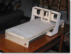
 When
I initially started cutting parts with the machine, I struggled with holding the
parts down on the table. I used various methods, but eventually settled on
using some metal strapping screwed down. I utilized some of the holes already
in the HobbyCNC tabletop design, and at each end and when to Home Depot and
bought some metal straps. They are heavy, and they roughly 1/8” thick. I used
one on the bottom of the material and the other on the top then had screws at
either end to effectively clamp them together. This accomplishes a few things.
First, it holds the part square and steady. Any movement whatsoever will cause
you to cut poor quality parts. Secondly, by having that 1/8” buffer between the
bed and the bottom of the material, it allows me to cut the material all the way
through without hitting the bed. This is an important concept and comes back to
the Z Axis.
When
I initially started cutting parts with the machine, I struggled with holding the
parts down on the table. I used various methods, but eventually settled on
using some metal strapping screwed down. I utilized some of the holes already
in the HobbyCNC tabletop design, and at each end and when to Home Depot and
bought some metal straps. They are heavy, and they roughly 1/8” thick. I used
one on the bottom of the material and the other on the top then had screws at
either end to effectively clamp them together. This accomplishes a few things.
First, it holds the part square and steady. Any movement whatsoever will cause
you to cut poor quality parts. Secondly, by having that 1/8” buffer between the
bed and the bottom of the material, it allows me to cut the material all the way
through without hitting the bed. This is an important concept and comes back to
the Z Axis.
The Z Axis usage changes now that we are not using a pen. The Z Axis has to be zeroed at the top of the material, and it must be carefully considered how far the Z Axis should plunge to A.) Cut the material and B.) Not hit the bed of the CNC machine. Analyze your GCode carefully and be sure you understand how the Z Axis will move.
Another concept that’s important with the Dremel and not with the pen is the concept of a sacrificial piece of wood under your material. If you picture a typical piece of 4x 30” balsa sheet lying across your CNC machine and attached at each end, you can easily imagine that the middle will sag no matter how tight the ends. For this reason I highly recommend you find yourself some balsa wood to put under the center of the material such that it does not sag and the bit can accurately and easily plunge through the material.
Dremel cutting bits are key components to your CNC machine. Do not, I repeat, do not waste your time with standard Dremel bits. The quality and nature of the cutting bits makes all the different in the world to your success. Contact http://www.thinktink.com for bits. They have bits of every shape and size and for every purpose. Even specific bits for cutting G-10 are becoming a very popular material.
You’ve tested your GCode by having the machine draw it. You’ve looked at your GCode carefully to understand the total movement, you’ve zeroed out the X, Y and Z Axis and now you are ready to go. I should suggest that there are a couple other tests you could run. In Mach3 you can “simulate” the run so you can watch the movement of the gantry on the screen in a simulation mode. If you are not using Mach3 there is a really neat simulator for Windows that is free located at (http://www.cncsimulator.com/) and in the beginning it really helped me to understand how the GCode would cause the machine to move.
I should mention one other important setting that is only marginally important with the pen as opposed to cutting the material. That is the concept of Feed rate. This is set during the creation of your GCode and will differ depending on the type of material you are attempting to cut. A 30” per minute is easy to plow through Balsa wood for example, but if you try that with G-10, the machine will each itself and may even cause damage. Because G10 takes much more effort by the cutting tool, you will have to slow down the rate at which the axis attempt to plow through. Keep that in mind.
I have greatly simplified things in this discussion to get you started. Some other examples of important points you will learn along the way are “Rapid movements” and limits, machine coordinate and homing. Stay excited about this project, take your time and try not to get overwhelmed.
With all of that said, the piece of material securely attached to your CNC machine and the GCode loaded, it’s time to start cutting. Turn on your Dremel, and give it a try. As Dave Platt says in his videos, “You will never learn to swim by doing the breast stroke on your living room floor, you need to get into the water.”
Session #10 – Summary
I suppose to some this process may seem a little daunting, but for guys who are building Remote Control Scale airplanes, this should really be a piece of cake to get going given enough time, enough help, and enough patience.
As I wrote this short document I began to think of the reasons I got into CNC in the first place. As I said I hated cutting balsa by hand, but the key reasons I can think of, perhaps retrospectively (and I am quite sure there are others) are as follows:
Accuracy – Computer generated parts are far more accurately
Repeatability – I can take a rib and repeat it EXACTLY the same way every time as many times as I like. If I have saved my work as a computer file I can cut the exact parts if I happen to have an accident, or want to give a kit to a friend.
Speed – Once I have set up the parts on the computer I can plow through balsa much more quickly than with a knife.
Less wasted material – The computer is so accurate and it allows you to lay parts out just like Great Planes would on a sheet of balsa, minimizing waste. The CNC machine is so accurate that it can even cut parts very closely together. You can actually design and fit everything before even touching a piece of wood.
More types of materials to cut. – Without my CNC machine I would be limited in terms of what I could do with G-10 for example. Even some ply woods were a pain.
Safety – I would argue that this machine is ultimately safer than using a band saw or a scroll saw. The spinning Dremel bit is dangerous but the blades of the saws are more so in my opinion.
There is a down side to all of this fun, and that is in the setup time. It definitely takes more time to develop the part in the computer and clean it up for cutting than it would to simply cut out a piece of paper and clue it to the material. By far the pros outweigh the cons on this project.
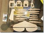
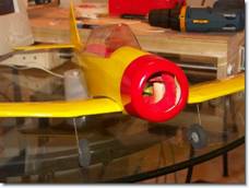
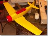
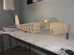
I started this article with a picture of an AT-6. That little plane was the first one I made from the CNC machine. Here are a couple more pictures which I hope inspire you to build your own CNC machine. I believe the original plan came from a copy of Model Airplane news a year or so back.
I’d like to mention one final project I’m working on (albeit a slow one) which is 100% CNC built. My Brian Taylor Mosquito, which you see in the picture below is in its early days was, but is built on the CNC machine using all of the methods discussed in this article. In fact I used the CNC machine to build the landing gear for the plane out of G10 which would be absolutely impossible otherwise.
I hope you found this Tutorial/Article useful, I’m sure there will be more to come.
I ask in return that you e-mail me and let me know how you made out. I’d appreciate any comments, feedback or ideas. I’m a Hobbyist, not a Machinist and I’m ok with that.
Written by:
Richard Wildey
Phoenix, AZ
e-mail: pilotjunky@hotmail.com