By Phil Clark
Making functioning landing gear doors
Why Bother!!
If we take a look at the majority of aircraft from the early 1940’s onwards,
especially military subjects, they all have one thing in common; they all have a
retractable landing gear. To accommodate this, large recesses are required in
the underside of the aircraft to accept the retracted landing gear, and for
obvious aerodynamic reasons, these recesses require covers that open and close,
in order to enclose the gear and clean up the airframe once the gear has
retracted.
|
 |
Many an
article has been written in the full size aviation press where gear
doors have been mentioned. The effects of missing doors, (from
failure or battle damage) or just a malfunctioning hanging door can
be quite noticeable, for instance, pulling to one side, minor
buffeting, decrease in top speed, etc, etc…My first question is
this, Why should our scale models be any different? Answer, They’re
not!
Gear
doors serve the simple purpose of improving the aerodynamic
efficiency of our aircraft once the gear is away. In addition to
this, we have the realism factor, if the full size had them, then so
should our models. Small operative features such as these add great
character to a model, and are not the fiddly nightmare that many
modellers view them to be. With a little extra thought and careful
attention, fully operative gear doors can be a reliable and
rewarding feature. |
Clamshells
This article will be
basing on WW2 fighters (namely P-47 and P-51) Both subjects have leg doors
covering the oleo and upper section of wheel, and a secondary ‘Clamshell’ door
that is actuated separately to cover the remaining lower section of wheel.
|
 |
|
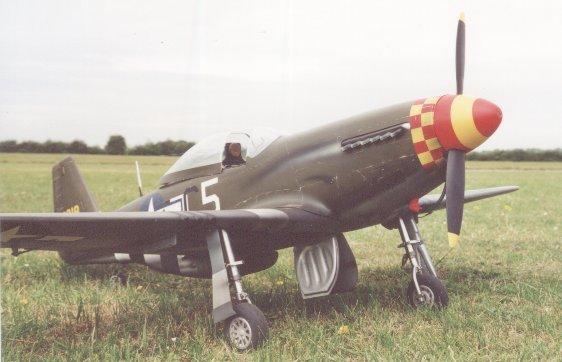
On the full
size P-51, when at rest, the doors droop down under their own weight,
only retracting to their normal closed position when hydraulic pressure
rises upon engine start. |
I’m not really going
to mention the leg doors too much here, as these are a little easier to model,
and don’t require a lot of ‘This is how‘. The motive force for this door is
often the leg itself, so if we try to copy the full size hinging and linkage
points, there won’t be too many problems to overcome. Even so, the leg door used
many of the same methods and materials as the inner door, so if you’ve not done
working doors at all in the past, keep reading!
Where to start
The first problem to
overcome is how are we going to operate these doors simply but reliably. We
don’t want a highly complex (no matter how clever) system, as the more complex
the method, the more prone to failure it’ll be. We don’t want doors flapping in
the prop wash because they are not held securely enough, just the same as we
don’t want doors opening and closing in the wrong sequence, so preventing
correct operation of the gear itself. A P-51 with the legs trying to retract
onto closed doors just doesn’t do it !
Over the last few
years, I’ve tried various mechanical methods of operating the doors, using the
retracting leg/wheel to pull the door closed and push it open again on the way
down. This method took a fair bit of fiddling around, and I was never 100% happy
with the end result, even resorting to throwing the doors away on one occasion.
Having no means of locking the door in the open position, they had a habit of
flapping as soon as the engine was started, and therefore fowling on the wheel
as it tried to retract past it. The method I have used on the last couple of
models is to drive the doors with miniature air rams, tapping off the main gear
supply for air. Using this method means the doors are held solid by the ram in
both the up and down position, hence, no more flapping.
Bits you’ll need
The heart of this
system is the retract spool valve. Ultra Precision of Ontario Canada
manufactures a great range of custom spool valves for a wide variety of
different applications. Two of which allow the modeller to sequence the
operation of the landing gear with the opening and closing of inner wheel well
doors.
The two valves in
question look identical, but vary slightly in operation. The U.P.2 is ideal for
the P-51, where upon selecting gear down, the inner doors open, the gear then
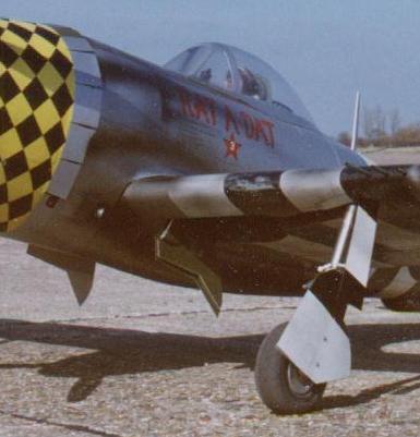
extends, and the inner doors close again. The U.P.3 (as used in the P-47 shown),
operates exactly the same, but doesn’t close the inner doors once the gear has
extended, they stay open. These valves contain small needle valves on the up and
down sides of all functions, allowing you to adjust the operating speed of the
legs and doors. Operating speeds for legs can be varied between 3 and 10 second
(nice and slow), and 0.5 and 3 second on the doors.
Miniature air rams
to drive the doors are available from various different sources. The Jet boys
seemed to pick up on these pretty early, BVM and Century Jet make various sizes
of ram, but the ones used here came from Ultra Precision. The size of ram you’ll
be looking for will depend on the size of model/door. To give you an idea, the
1:6 scale P-47 shown uses rams of ¼” diameter, and 1” travel, this gives plenty
of moving/holding power, and just the right amount of movement. The P-51 doors
are a little larger; so a little more power is required, so the next ram
diameter up was used (5/16’’)
Here’s how
In order for the
doors to open and close fully, the geometry of all the pivot points has to be
correct. You can’t do this simply by trial and error; you’ll be there for hours.
The simplest and most reliable method is to go get the paper, pencil and
compasses out, and draw it out by hand (accurately!).
First off, you must
accurately draw a cross section through your undercarriage well. Mark the
position of the door pivot point, and draw the door on in its open and closed
position. You’ll have to refer to your documentation here, as not all systems
opened through a full 90 degrees. Make sure you get it right for the model your
building, it’s the little things that if wrong can make your model look
decidedly strange. Next job, draw on the door actuating horn and the pivot point
of the ram on the horn. It is the position of this horn/pivot that will
ultimately get the doors operating correctly, a good starting point would be to
have the horn pivot 15mm inboard of the door pivot, and around 10mm off the
surface of the door itself. Mark the horn/pivot on the open and closed-door
position, making sure they’re both identical though!
The next stage is to
measure the exact length of the air ram from the centres of the pivot points at
either end. Most rams usually have some form of bracket at the fixed end, and
the plunger is threaded to accept a small ball joint. Carefully measure the
length in it’s closed position, then add on the amount of travel to give you the
open length. Back to the drawing, with a pair of compasses, set the distance to
the closed length and draw an arc with the point of the compass on the door horn
pivot in it’s closed position.
Next, open the
compass out to the open length and draw another arc, but with the point on the
door horn pivot in its open position. Wherever the two arcs cross is the pivot
point for the fixed end of the air ram. As happened a few times with me the
first few times I tried it, the crossing arcs ended up outside the wing skin, or
in such a shallow position, the ram wouldn’t open the door. As I mentioned
earlier, the remedy for this is to play around with the position of the door
horn and it’s pivot point. You’ll be surprised how a movement of only a few
millimetres in either direction can make all the difference.
The result we are
looking for, particularly with a model such as the P-47 where the wheel wells
are spread well apart, is for the ram to be contained completely within the
wheel well, with the direction of ram movement to be no less than ¼” outboard of
the door pivot itself (see drawing). Any less than this, and the angles are
getting pretty tight which will prevent the ram from easily moving the door. If
you are modelling a type such as the P-51 or later model FW 190’s (Ta 152) where
the wheel wells almost touch in the centre, your task is a little easier. You
will be able to mount the rams almost vertical in the wing, with the fixed pivot
protruding through the top skin of the wing, but concealed within the fuselage.
Put theory into practice
Right, we know where
everything has to go, but the construction has to be equally as accurate if you
are to have successfully operating doors. The first constructional decision is
to decide upon an appropriate material for the doors themselves. I have tried
several different materials over the years, some with better results than
others. If your subject has doors with only a single curvature, you have a
choice of around 3 materials. If your subject has highly shaped doors, such as
the Bearcat, your only real option is to mould them from fibreglass.
Material choice
Back to the simpler
doors of the P-47, your first choice would be 1/32” plywood. Easy to work with,
but needs a reasonable amount of surface preparation before they are ready for
detailing and installation. The other downside to thin ply in this application
is that it is easily damaged. The doors have a pretty hard life, they get used
at least twice a flight, and get a real battering if the dreaded belly landing
situation occurs, or a leg collapses.
Your second choice
is thin aluminium sheet. Again, easy to work with, easily formed to the curved
profile of the wing, but in my experience, not very durable. The aluminium is
very soft at this thickness, so scratches and bends very easily, even a little
scrape getting the wing from the car can catch an edge, bending and damaging the
door. The best material I have found is a thin fibreglass sheet called G –10.
This material is only around 1/64” thick, very flexible, but incredibly tough.
Polyply, a BVM product would do a similar job, and is available in various
different thicknesses.
Fabricating the
doors is straight forward enough, but you must decide whether you want your
doors to be exactly the same size as the well, so requiring a series of small
door stop blocks positioned around the inner lip of the well to stop the door
flush with the wing surface, or, to make the door around 1mm larger all the way
round so the door sits on top of the wing surface. This method may not be 100%
accurate, but is a lot less fiddly and is the method I used on the P-47. With
the doors all closed up, the 1/64” thickness of the G-10 is not really
noticeable, especially when you have invasion stripes and weathering to disguise
it.
Hinging
Hinging of the doors
is done simply with conventional pined control surface hinges. The one thing I
will say is don’t glue the hinges to the wing and the door. Why? If the door or
hinge does sustain damage and needs removing, gluing the hinge will make your
job rather difficult. I have always attached the hinges to the door using small
M2 or 12/14BA nuts and bolts. Most hinges have glue-keying holes moulded in, so
why not use them!
To attach the hinge
to the wing, epoxy some snake inner into the balsa wheel well wall, and screw
the hinge to these using small self-tapers. This method will allow a complete
disassembly to be carried out if required. Perhaps the most critical area is the
door horn and pivot. I have found it a good idea to make this detachable from
the door too; modifying a conventional small plastic control horn is ideal for
this part. Just make sure you check your positioning measurements 2/3 times
before you start drilling holes etc.
With the critical
work on the doors complete, the last job is to position the fixed pivot for the
air ram. Again, check and recheck your dimensions before you do any drilling. To
mount the ram, I use the same method as for the doors. Sink a length of snake
inner into the wheel well wall, leaving enough protruding so that when the ram
is tightened down onto it, the ram body doesn’t fowl the well wall. The type of
screw used for fixing is also important. I wouldn’t recommend a self taper
threaded all the way down, the ram has to pivot a little in it’s mounting, a
threaded screw will end up wearing away at the mounting hole. The best screws
are the servo mount types that have a ¼” non-threaded section at the top, nice
and smooth, no wear problems.
Internal detail
The only time people
will see the gear doors is when the model is on the ground with the doors open,
all the more reason to put a little effort into detailing the inner surface to
add that finishing touch. Very few aircraft had single skinned doors; most had
some thickness to them or a simple stiffening structure on the inner surface.
This detail is simple to add from blue foam covered in paper, or balsa with
several coats of dope to seal prior to painting as used on the P-47. For the
simple stiffening structures, plastic ‘I’ and ‘T’ beam can be ZAPped in place to
give a simple but realistic appearance. This technique was utilized on the upper
leg doors on the P-47.