Researching An Airplane The Physical Way
By Stephen A. Carr ( February 2004 )
In the days before the Internet, researching an airplane for a future model meant buying books, magazines, and three view drawings for use as reference. These days, most of the information on a prototype can be found by browsing the net. Data tables, photographs, three views, pilots notes etc can be found for most airplanes built, if you search hard enough. However, if you want to build an accurate scale model, particularly one airplane mark out of many different versions, you cant beat getting up close and personal.
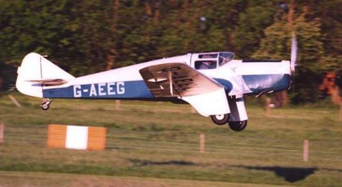
This article, which I was press ganged into writing by Phil “p51p47”, is an attempt to aid the modeller into the methods I use of researching a full-size airplane to enable an accurate model to be produced. The prototype under the tape measure is the Miles Falcon Major; my next project after the Northrop N-9M Flying Wing is complete. This four-seat cabin monoplane was built in 1936 and is still airworthy in the hands of a private collector. The aircraft was an air racer and the type won and took many high places in the King’s Cup Air Race. It is currently based with the Shuttleworth Collection, at Old Warden, Bedfordshire, England.
This next bit is ‘real important’ for this method of research to work. You need to find an example of the airplane you wish to model in a museum, or privately owned, and contact the owner. This can be done via the museum, the flying club where the plane is based, or possibly even locating the owner by tracing the airplane registration through the National Aviation body.
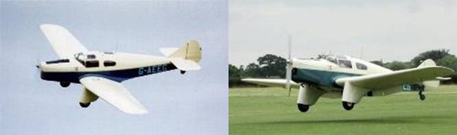
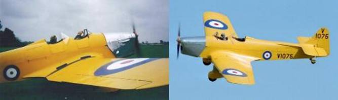
Once the owner is known, write to them explaining that you wish to build a flying scale model of their airplane. Send a few photographs of previous models you have built, as it will show the owner that you are serious and capable. Most full-size airplane owners are very proud that somebody wants to model their airplane and are usually very helpful. If you are lucky, you may be invited for a flight in the aircraft. I was lucky, and received rides in both the subject of the article, the Miles Falcon, and the owners other aircraft, the Miles Magister, both very rare types with only two Falcons and three Magisters surviving in an airworthy condition.
Above: The Miles Falcon Major and Below: the Miles Magister
OK, so you have chosen the plane, found the owner, made contact and arranged a date to visit to photograph the airplane. Bear in mind that this will take a full day if done correctly, so warn the owner of the airplane that you will be some time. What do you need to take? Well, before you take anything anywhere, you could do with a bit of paper research. If you can trace one, find a good 3-view drawing. Make a copy and enlarge it, if needed, so that you can write dimensions on it. Also very useful if you can find one is a plastic kit of the airplane. It’s not needed at this stage, but will be invaluable later when it comes to reproducing the 3-dimensional shapes a 3-view drawing can’t show.
First of all you will need a 35mm camera and probably about four 36 exposure films. The speed of the film depends on whether you’ll be working in a dark hangar or in bright sunlight. Remember that if you are working in a hangar, you don’t want the camera flash operating, which will cause white out on all of the pictures. An aid when taking photographs is a small ( or large ) pair of step ladders. These will allow access to out of reach areas on a tall airplane or allow pictures looking down on the upper surfaces. A large pad of blank paper is also worth taking. You can use this to sketch parts, make rubbings of hatches, window frames etc which can then be scaled later.
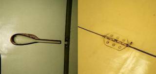
Tracing paper is also very useful for copying lettering and their positions relative to other parts. Another useful trick with tracing paper is to draw a one inch grid on the paper in bold black ink. This can then be laid over various details and photographed. In the case of small stencil details and other small lettering or logos, take one picture with the tracing paper over to give scale. The grid will allow the size of the image to be scaled to suit the model. Take another without the grid, which can be enlarged to the correct size and possibly cut out, made into decals or used as reference for hand painting. The more measurements to can make, the easier the model build and finishing will be later.
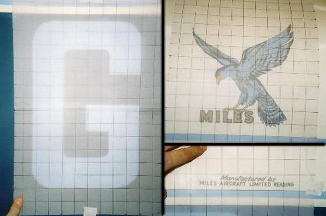
The tracing grid over a registration letter, the Miles logo and small stencil detail.
For those little curves, vents lumps and bumps, a profile gauge is a useful tool. It is the tool that builders use to mark odd shapes on skirting boards etc., prior to cutting, so that they can mark an accurate reproduction of the shape to be cut out. It can be pressed onto the curved surface of a vent for example, and then that shape transferred to paper for scaling later.
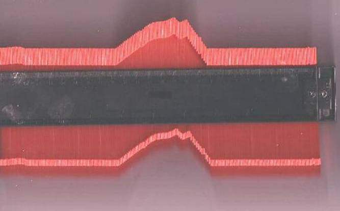
A profile gauge
A large tape measure is essential, at least 5 metres ( 16 feet ), so that you can measure wing spans, chord length etc. A 3-view drawing may be good, but it is always worth getting measurements from the full-size airplane, you never know whether the drawing is 100% correct. At the very least, you should check all the major dimensions such as length, span, height, wing and tail chord etc. A plumbers line is also very useful for projecting positions down to the hangar floor for measuring, such as the wingspan, and chalk or masking tape to mark the position on the floor.
String is also a useful tool you will need. With this you can tape a centre or datum line to the plane from which measurements can be taken of fuselage widths for example. A tool connected with this is a set of large callipers. I made a balsa wood set with arms around four feet long, though the size really depends on the airplane to be measured. If you’re building a B-36 peacemaker for example, you may be better off with a global positioning system rather than string and a tape measure! With the string and callipers, you can mark a datum line and measure widths and lengths of fuselages, wings etc., from the datum.
|
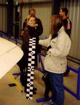
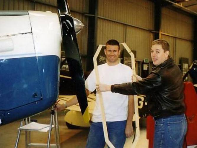
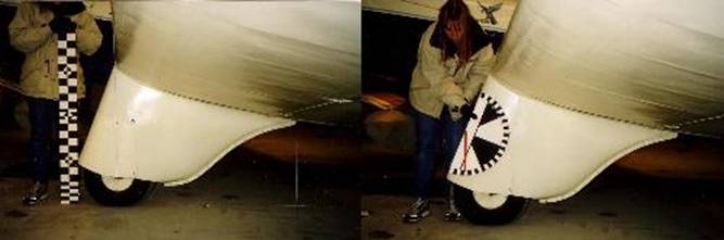
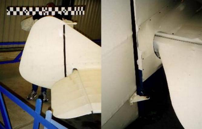
The next tool I have found to be invaluable, and that is a large measuring stick. Find a strip of wood about 4 inches wide and paint on it black and white checks of two inches square. The first six inches can be painted in 1 inch markings. Every foot, paint a round target so that feet can be counted easily.
The picture to the right shows Nicky and Lynne, two of my helpers for the day, along with the four feet length measuring stick. |
|
|
|
This tool should be in almost every photograph you take. When held along side the part being photographed, providing the photograph is being taken square on, it can be used when plan drawing and building, to scale objects off the photograph.
It is no substitute for measurements, but there will always be bits you missed or ran out of time for. This way, you can still guesstimate many part sizes very accurately from the divisions on the ruler in the picture. |
Another homemade tool I use is a gravity-operated protractor. Sounds technical, but it isn’t really. It is just a large wooden protractor divided into 5 degree divisions with a wooden, weighted pointer which will always point down. This is another tool that is held in place during photography to assist with checking the angle measurement of your drawings.
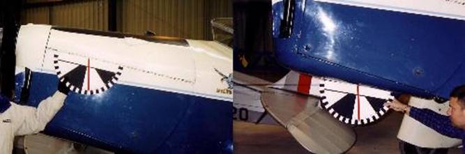
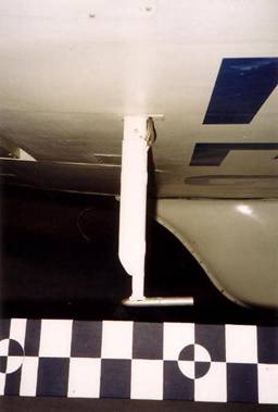
These two cowl pictures confirm that the hinge line is parallel to the underside.
The final “Tool” that you should bring is a willing, or at least semi-willing volunteer. It’s no good having all of these tools available if you don’t have someone to hold them while you take the pictures, or someone to hold the other end of the tape measure! I usually take my wife ( or girlfriend if my wife’s busy ). Another modelling friend will do just as well as they only have to stand and do what they are told. On second thoughts, getting the wife to stand and do what they are told could be problematical; take a friend!
Plan the order you will work in. Start with the photographs, that way if you run out of day light, you can still measure using artificial light. Write a list of all the parts you want to photograph, allowing three or more pictures of each part ( ie front, end and plan ). Try to take the pictures as square on to the parts as possible to reduce perspective and distortion.
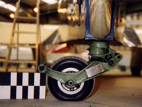
Use your photo list to methodically work around the plane, starting from the front taking pictures of the front of the plane. Whether a ‘Trike’ or tail dragger, you’ll need plenty of landing gear pictures, particularly if they retract and have wheel doors too, so this is a good place to start. If they are particularly complicated, and you may be building them yourselves, or getting someone else to build them for you, take 3-views of each part if possible, as well as general arrangements. Detailed measurements will also be vital here if the geometry is to work correctly.
With the gear out of the way, begin at the nose or engine cowling. With a single engine airplane, there will be lots going on in the nose ( unless the airplane is an odd configuration! ). There will be lots of removable panels on the cowl and nose to access the engine and secondary equipment. Intakes, vents, cowl fasteners, exhausts etc. Then there is the propeller blades and hub detail if you will be making a static prop.
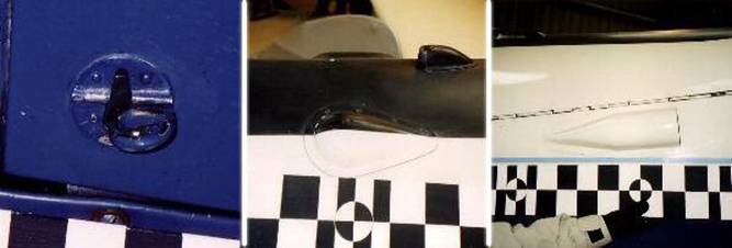
Engine cowling details such as fasteners, blisters and intakes can make or break the look of the finished item.
|
Next move onto the starboard wing, starting at the root fairing, working along the front of one wing, including intakes, stall strips, slots, slats etc, wing tip, trailing edge, aileron, flap and trailing edge fairing. You may want to use the profile gauge at this point to copy wing fairing shapes etc. |
|
|
|
Check the top of the wing for hinge details, landing gear or flap position indicators, as many airplanes have small pop up pins or flaps as a manual indication of the control position. Trim tabs and their linkages, balance weights and navigation lights are further items you are likely to find. |
|
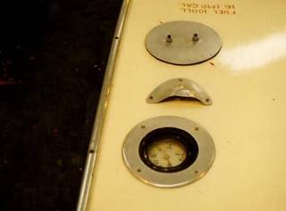
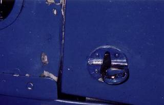
Fuel tanks are often located in the wings, so don’t forget the fuel and oil tank caps, plus any stencil data associated with them.
At wing joints, there may be noticeable structure on the surface such as interesting panel or rivet detail, wing strut fixings, or removable bolts and pins for airplanes with folding wings. |
|
Move on down the fuselage, taking pictures of windows, vents, registration, aerials, doors, hand and foot holds etc. You will be surprised at how much there is to photograph on even the simplest of airplanes. At the tail, you may have a tail wheel if a tail dragger, but even without, the tail feathers can be quite complex. There are the basic structures, which you need to photograph in front, side and plan forms if possible. There are the fairings, access panels to control rods or cables, the control cable outlets themselves, control horns, hinges, nav and collision lights, trim tabs and actuating mechanisms. Don’t forget the shrouds around the hinged surfaces. Also found on the tail can be vortex generators and turbulators.
Now we move back along the other side of the fuselage. Don’t assume that it will be the same as the first side. The fuselage squadron codes if a military airplane, may be in a different order or position to the first side due to other structural features ( such as the B-17’s staggered waist windows ). Work around the other wing now, looking out for the same features as on the first, ie flaps, ailerons etc, but also pitot tubes and static vents etc which may only feature on one wing. U.S. national insignia was often only on one wing ( ie port top and stbd bottom ).
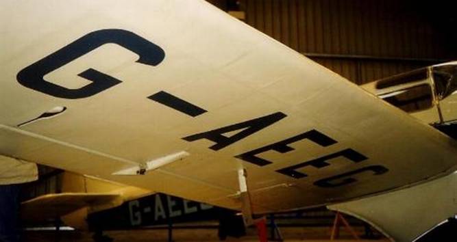
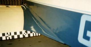
This underside wing picture shows the large registration, pitot head, aileron actuation linkage and fairings and aileron balance weight. Also noticeable are the rib positions below the plywood skin.
If you are building to a large scale, you may also want to photograph all the stencil warning and data panels. Remember to plan ahead and take plenty of film with you. If you had to make a long trip to visit the airplane, you don’t want to miss anything out.
If the airplane is multi-engined, each cowl and nacelle could be ‘handed’ and are not always mirror images. Check each one for variations. Military airplanes have ‘military bits’ in addition to the basic assemblies of an airplane. A bomber for example will have turrets at various locations, a bombardier’s position, bomb doors or bomb racks. These will also need to be pictured in detail as gun turrets often came from different manufacturers, and so were not common amongst aircraft of different marks. Restorations may not have the correct type of turret due to availability of surviving components.
|
Remember to take some general views of the airplane, as these show how weathering shows on the plane and how it follows the airflow around the airframe. If the aircraft is stored outside, there will probably be vertical rain/dust streaks down the airframe in addition to the airflow driven oil and dirt. Even museum operated aircraft leak oil and suffer fretting and chipping around cowl fixings etc.
|
|
Also be aware that modern restorations will have aerials, lighting and cockpit instruments to comply with current regulations. If you are building the aircraft as it was during its service life, there will be differences in layout of equipment. Be careful not to build a generic model. Try to find different sources of information that agree with each other.
With photographs complete, it is time for measuring to begin. This is where preparation will save you time. If, prior to your visit, you can find a reasonable number of photographs, you will be able to draw out many of the parts of the airplane in your sketchpad. Even if you have a 3-view drawing, sketch as many parts of the plane, large and small, as you can. Try to be as complete as possible, sketching out every intake, registration codes, serial number, hatches, fuel tank caps, windows, turrets, wheels and legs etc., and draw onto the sketches, ‘empty’ dimension arrows of all the significant dimensions.
With this done beforehand, you have plenty of time to look over them and see if there are any areas which you have missed. Once at the airplane, you need only go around measuring and filling in the numbers. It is so much easier this way, than to try to sketch out the parts while you are there. You will always find some detail on the airplane that you didn’t draw beforehand, but at least these should be minimised.
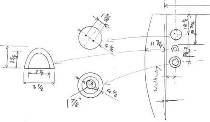
Sketch of fuel tank cap and quantity gauge
With a large airplane, it is worthwhile splitting the tasks with a friend who can go around taking the pictures while you begin measuring. It took myself and a friend a good sixteen man hours photographing and measuring the RAF Museum’s B-17 back in 1988, and there were still many areas that we missed, resulting in visits to the Imperial War Museum to see B-17’s “Sally B” and “Mary Alice”.
Once you have taken all the pictures, measured everything and left, don’t forget the planes owner. Keep in contact, and send pictures of your construction progress. The owner is more than likely going to be just as interested in the model as you are. If you are brave, you could always invite them to the test flight, and it is always nice to have a photo opportunity with the model in front of the full-size for when you write the magazine article!
Now you can draw your plans, or check that the plans you are building from are correct, and modify them as necessary. The measurements you have taken, along with the photographs, should be more than ample, together with a 3-view, to make an accurate, highly detailed scale model. With that done, get the knife out and start some serious balsa bashing.
I hope you enjoyed the read and found something worthwhile to make your future projects a little easier and more scale like. Construction of this ¼ scale, 9 feet span model is yet to begin, but I hope to start within the year. Watch out for the Miles Falcon in the “Show Your Stuff” section of the forum. If you have any further questions, please feel free to e-mail me at:-
stephencarr@usaafhq.freeserve.co.uk
Also check out my U.S. Army Air Force Model Display Team website at www.usaaf.org or www.usaaf.co.uk and my business website www.a2artwork.co.uk for further examples of my work.